


SCHNEIDER DIGITAL MICROPHONES FOR HIGH RESOLUTION AUDIO
AES 31st International Conference, London, UK, 2007 June 25–27
5
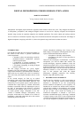
higher frequent white noise components. One possible
way to reduce this effect is a non-linear network,
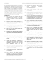
keeping both ADCs always in operation, and summed,
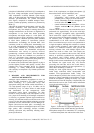
depending on the signal level, as shown in Fig. 9 & 10.
Figure 9: Gain ranging ADC circuit, with non-linear
network [10]
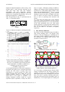
Figure 10: Separate signal paths and re-combination
result in circuit of Fig. 9, with non-linear crossover
topology [10]
As mentioned, the gain ranging ADC shown in Fig. 7 is
a floating-point processor with exponents of 2
0
and 2
4
.
Combining them does widen the dynamic range by
4x6 dB = 24 dB, but does not improve their specific
resolutions. Such a simple switching circuit will then
modulate from the lower range ADCs noise to the
higher range ADCs noise whenever the signal passes the
crossover point, producing a distinct noise peak. A non-
linear crossover network smooths this transition region
out, making it inaudible. Properly designed, the result
can then be a digital microphone with a dynamic range
of up to 130 dB-A, with all noise components 80 dB
below the signal over a wide dynamic range.
5 APPLICATION BENEFITS
From the above, some benefits for the user become
immediately clear. With up to 130 dB-A, the dynamic
range of the conversion covers the complete dynamic
range of the analogue microphone counterpart. There is
no need anymore for setting the gain controls in order to
match input and output levels, as needs to be done with
standard analogue recording set-ups. When recording to
an appropriate 24 bit medium, the digital microphone
can be connected and recorded directly, any gain
levelling taking place after the recording, or just for
monitoring purposes. The lower limit for the signals is
determined by the self-noise of the capsule, thus by
unavoidable physics, and the maximum allowed sound
pressure levels cover the vast majority of applications.
For very loud signals, the dynamic range of the capsule
output and thus of the complete digital microphone can
be shifted by e.g. 6, 12, or 18 dB with the same
mechanisms as in analogue microphones (shunt
capacitance, negative feedback, or reduced polarization
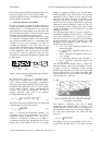
voltage). For safety purposes, an additional very fast
look-ahead peak limiter (see Fig. 11) implemented
inside the microphone takes care of unforeseen
excessive sound pressure levels.
Figure 11: Signal flow in a digital microphone, with
compressor and peak limiter
All this holds of course only true for the described
professional digital microphones with very wide
dynamic range, which the AES42 standardization
committee had in mind. Other recent microphones with
digital interface, powered by USB, show a very limited
dynamic range, often with a noise floor consisting of
undithered ADC quantization noise plus power supply
artefacts, and thus offer no advantage over their
analogue counterparts, other than simple connectivity to
PC environments [14].
One side note has to be included, regarding current
digital recording and monitoring equipment: Often,
these devices are so designed as to expect only digital
input signals aligned close to reference studio level, and
accordingly only offer limited gain manipulation, e.g.
+10dB, of such digital signals. As has been shown in
Fig. 5, digital microphones can be recorded directly
with the widest dynamic range if they are operated with
no
or small digital gain and do not require pulling up the
gain as high as possible. Still, and be it only for direct
monitoring purposes, those perfectly recorded low-level
signals need to be made audible. It would be helpful
then, to find more digital recording equipment offering
amplification of digital
input signals, and not only the
analogue ones, over a wider gain range.
6 OUTLOOK AND CONCLUSION
Microphones with digital output are a comparatively
new concept. Still, they show clear advantages
regarding gain settings and dynamic range handling, and
0s 0.5ms 1.0ms 1.5ms 2.0ms 2.5ms 3.0ms
Time
V(Path-1) AND V(Path-2)
100mV
0V
-100mV
V(Path-2) V(Path-1)
100mV
0V
-100mV
“No signal”
controls noise gate
via DSP
Path-2
Path-1