


10
US
GB
11
US
GB
1. Introduction
This manual contains essential information for the
operation and care of the product you have pur-
chased. Please read the instructions carefully and
completely before using the equipment. Please
keep this manual where it will be accessible at all
times to all current and future users.
Additional information, in particular concern-
ing available accessories and Neumann service
partners, can be found on our website: www.neu-
mann.com. Information about service partners
can also be obtained by telephone: +49 (0) 30 /
41 77 24 - 0.
The following related fi les are available in PDF
format in the Downloads section of our website
www.neumann.com:
KM D Operating Manual – Digital Miniature Mi-
crophones
D-01 Operating Manual – Digital Large-Dia-
phragm Microphone
Brief Description of the AES 42 Standard
Additional information concerning the digital mi-
crophone interface can be found at http://www.
aes.org/publications/standards/ under the title
“AES standard for acoustics – Digital interface for
microphones”.
The Neumann online forum enables Neumann
users worldwide to share their experiences.
Through its integrated archive function, the forum
has developed into an extensive knowledge pool.
2. Safety instructions
The DMI-2 Digital Microphone Interface has the
intended purpose of providing power and remote
control for digital microphones in accordance
with the international standard AES 42, and of
making the audio data stream from the micro-
phone available in AES/EBU format for recording
or further processing.
Connect to the inputs only microphones that
comply with the AES 42 standard.
Connect the outputs only to AES/EBU inputs.
The RJ-45 ports of the DMI-2 have a DC
voltage, and must not be connected to an
Ethernet.
•
•
•
•
•
Repairs and servicing are to be carried
out only by experienced, authorized ser-
vice personnel. Unauthorized opening or
modifi cation of the equipment shall void
the warranty.
Allow the equipment to adjust to the ambient
temperature before switching it on.
Do not operate the equipment in a damaged
condition.
Always run cables in such a way that there is no
risk of tripping over them.
Ensure that liquids and electrically conductive
objects unless required for operation are kept
at a safe distance from the equipment and its
connections.
Do not use solvents or aggressive cleansers for
cleaning purposes.
Dispose of the equipment in accordance with
the regulations applicable to the respective
country.
Please note: All information relating to the micro-
phones refers to digital microphones of the Neu-
mann Solution-D series.
Disclaimer:
The product is sold “as-is” and the customer is as-
suming the entire risk as to the product’s suitabi-
lity for his needs, its quality and its performance.
In no event will Neumann be liable for direct,
indirect, special, incidental or consequential da-
mages resulting from any defect in the product or
from its use in conjunction with any microphones/
products from other manufacturers, even if advi-
sed of the possibility of such damages.
3. Description
The DMI-2 provides power and remote control for
digital microphones that operate in accordance
with the AES 42 standard (see www.aes.org).
Connected microphones are supplied with power,
and the audio signals received are output in the
AES/EBU data format (AES 3).
The DMI-2 provides for communication between
digital microphones and a PC/Mac with the Neu-
mann RCS remote control software, and generates
the required control data. In addition, synchroni-
zation of the microphones is carried out via an
external or internally generated word clock.
•
•
•
•
•
•
The most important functional features of the
DMI-2 are as follows.
Power is supplied to two digital microphones
(in accordance with the AES 42 standard).
The audio data stream is received from the mi-
crophone and is output as an AES/EBU signal.
The microphone is synchronized with an exter-
nal or internally generated word clock (using
automatic detection).
All standard sampling rates are supported:
44.1 kHz, 48 kHz, 88.2 kHz, 96 kHz, 176.4 kHz,
and 192 kHz.
Asynchronous operation is supported. In this
case the audio data stream is made available
at the AES/EBU output with the sampling rate
recovered from the microphone signal.
A computer interface is provided for transmit-
ting and processing bidirectional control data.
For this purpose, Neumann supplies control
software that can be operated on a PC or Mac
(the RCS Remote Control Software).
The user port provides for direct control (via a
switch contact or low-active signal) of selected
functions (Mute, LED 1 and LED 2).
Multiple devices can be cascaded.
Internal memory: All settings are retained af-
ter the DMI-2 has been switched off . After it is
switched on again, these settings remain in ef-
fect even in the absence of a connection to the
computer [stand-alone operation].
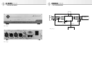
Indicators (Fig. 1)
Power
Indicates that the equipment is ready for opera-
tion. During the startup process, the indicator
shines less brightly.
Data Valid
Indicates a valid AES 42 data stream from the mi-
crophone to the DMI-2.
Sync Locked
Indicates synchronization of the microphone with
a master word clock. The indicator blinks while
the microphone is being synchronized. It shines
continuously when the microphone has been suc-
cessfully synchronized.
•
•
•
•
•
•
•
•
•
Ext Word Clk
Indicates an external word clock. The indicator
does not light up if no external word clock signal
is detected. The indicator blinks if a signal is pres-
ent at the external work clock input but synchro-
nization has not (yet) been achieved. The indica-
tor shines continuously when the DMI-2 has been
successfully synchronized with the external word
clock. Prolonged blinking of the indicator means
that although a signal is present at the word clock
input, it has not been interpreted as a valid signal;
the cause may be an invalid word clock frequency
(+/-50 ppm) or very high jitter values.
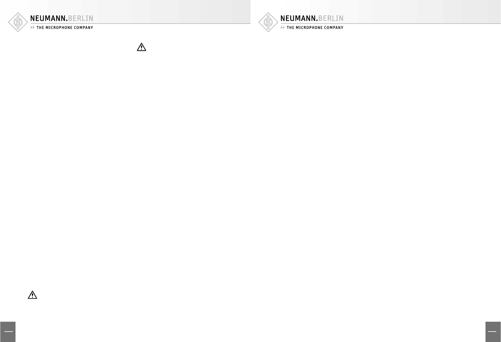
Ports (Fig. 2)
Master Clock In/Out
In digital studio setups, a central master word
clock is usually used for synchronizing the con-
nected equipment. The DMI-2 automatically syn-
chronizes itself with this external word clock as
soon as such a signal is detected at the word clock
input (BNC, 75 ohms).
If there is no valid word clock signal at the input,
the DMI-2 automatically activates an internal
word clock generator. The word clock frequency
corresponds to the sampling rate of the synchro-
nously operated microphones (see “Synchroni-
zation” section). The signal provided for other
equipment at the Master Clock Out word clock
port is therefore the external word clock signal
that has been received or the internally generated
word clock signal.
Even in the absence of power, an external word
clock signal will be transferred by the DMI-2 di-
rectly to the Master Clock Out port. If no cable has
been attached to the output of the external word
clock, an automatic termination (75 ohms) is ef-
fective at the word clock input.
For hardware version 03 or above:
An AES 11 signal can also be used as an exter-
nal word clock signal.
Even in the case of external synchronization,
the internal (VCXO) clock generator remains
active and is synchronized with the external
word clock by means of a phase-locked loop
(PLL). This provides very eff ective jitter sup-
pression.
•
•