


16
US
GB
17
US
GB
8.4 Synchronization
The AES42 standard describes the following two
modes for synchronizing the microphone with the
receiver (e.g. a mixing console or the DMI-2 Digi-
tal Microphone Interface).
Mode 1: The microphone operates asynchronous-
ly, using the sampling rate of its internal quartz
oscillator. In this case, a sample rate converter is
required at the receiver.
Attention: This mode should be used only when
it is not possible to use mode 2 synchroniza-
tion, since signal quality can be expected to be
impaired by standard sample rate converters (in
terms of dynamic range and latency time).
Mode 2: The microphone operates synchronously
with a master word clock. This can be an exter-
nal word clock, or the internal word clock of the
DMI-2. In this case, a frequency/phase compari-
son with the master word clock is carried out in
the AES 42 receiver. A control signal is generated
which is transmitted via the remote control data
stream to the microphone, where it controls the
frequency of the internal quartz oscillator.
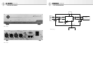
Via the BNC output, the internal word clock gen-
erator can be used to synchronize additional
DMIs and connected equipment, such as a mixing
console.
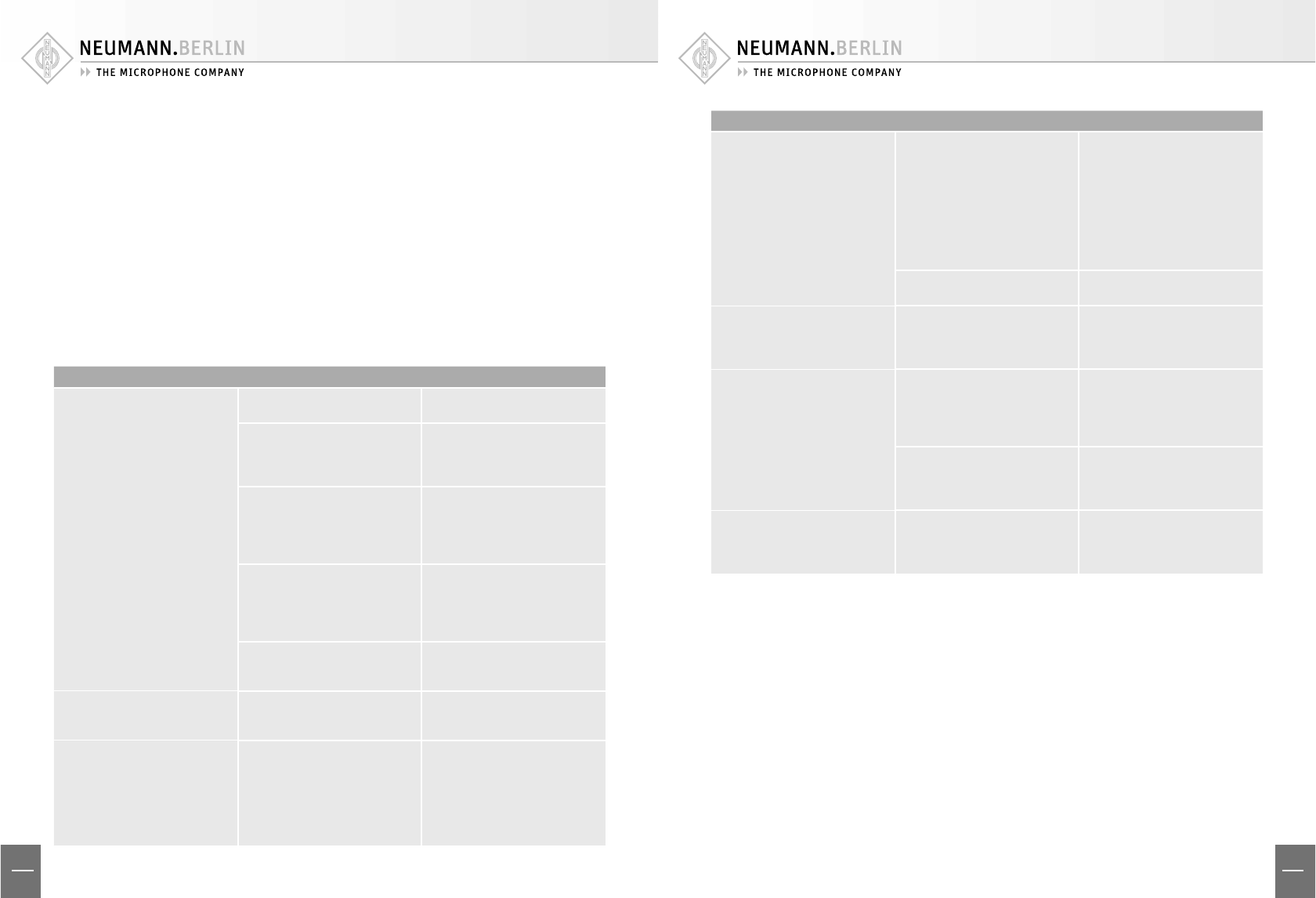
9. Troubleshooting
Problem
▶
Possible causes
▶
Solution
The RCS does not indicate that a
microphone is switched on and
connected to the DMI, even though
the “DATA VALID” LED on the DMI
is lit up.
The DMI is not recognized by the
RCS software. – Cause:
The DMI was not switched on
at the time when the RCS was
started.
Do not start the RCS until the DMI
has been switched on; or execute
the command Options/DMI and
then close the window again.
An ID has been used that is not
currently supported by the RCS,
or the same ID has been used for
more than one DMI.
Currently only the IDs 0, 1, 2 and
3 are supported. Set the ID by
means of the coding switch on the
back of the DMI; each DMI must
have a diff erent ID!
The ID has been changed while the
DMI was in operation.
After an ID is changed, the DMI
must be restarted. Then restart
the RCS; or execute the command
Options/DMI and then close the
window again.
Incorrect interface setting (USB,
COM1 or COM2).
Select the correct interface in the
RCS via the command Options/
Communication.
The “Ext. Word Clk” LED is not lit
up, even though an external word
clock has been connected.
No word clock signal has been
detected.
Check the source of the word clock
signal and the cable connection.
The “Ext. Word Clk” LED blinks
continuously. (Blinking for a short
period following activation of an
external word clock is normal, and
indicates that the synchronization
process is being carried out).
A word clock signal is present,
but has not been interpreted as a
valid signal. This can occur, for ex-
ample, if the word clock frequency
deviates by more than ±50 ppm
from the nominal value.
Check the word clock frequency or
select another source for the word
clock signal. Alternatively, remove
the external word clock and use
the DMI internal word clock as the
master word clock for the signal
chain.
Problem
▶
Possible causes
▶
Solution
The “DATA VALID” LED is not lit up,
even though a microphone is con-
nected and switched on. (The RCS
“AES 42 PWR” display is lit up).
No valid data stream – Cause:
The microphone cable connection
is faulty or too long.
Check to ensure a continuous
cable connection.
Comply with the recommended
maximum cable length and
required cable quality, as appli-
cable for the selected word clock
frequency. Avoid unnecessary
transition points (connectors). See
Section 8.2, Cables.
The microphone is defective. Use a microphone that is in good
working order.
The “SYNC LOCKED” LED blinks
continuously. (Blinking for a short
period during the synchronization
process is normal).
The microphone has not been
synchronized because the se-
lected word clock frequency is not
supported.
Select a word clock frequency that
it is supported by all of the con-
nected microphones.
The “SYNC LOCKED” LED is not lit
up.
The microphone is operating in
asynchronous mode. (This is indi-
cated by the letter “a” preceding
the frequency display in the RCS
word clock window).
Set a sampling rate for synchro-
nous mode or set “Sync to Ext.
Word Clk”.
The microphone supports only
“mode 1” in accordance with the
AES 42 standard, i.e. it cannot be
synchronized.
Use a microphone that can be
synchronized (e.g. any Neumann
Solution-D series microphone).
Functions cannot be controlled via
the user port.
Control via the user port has not
been activated.
In the RCS system menu, “Func-
tion controlled by user port”
must be activated for the relevant
functions.