


14
US
GB
15
US
GB
Start the RCS program, or if necessary restart it, if
the program was already on.
Attention: The DMI-2 must always be switched on
before the RCS is started, so that the DMI-2 will be
detected by the PC or Mac. While the RCS is op-
erating, the cable connecting the computer to the
USB 485 converter must not be disconnected, so
as to prevent uncontrolled behavior of the com-
puter. This requirement is due to the specifi ca-
tions of the USB interface.
Long modulation cables and multiple connections
lead to a drop in the microphone supply voltage
and to a deterioration of jitter behavior, particu-
larly in the case of high sampling rates. Therefore,
if possible, use continuous cable between the mi-
crophone and the DMI-2, and between the DMI-2
and subsequent equipment. For longer distances
use AES/EBU cable exclusively (with an imped-
ance level of 110 ohms).
Ensure that the microphone and all devices in
the digital signal chain are synchronized. Micro-
phones connected to the Neumann Digital Micro-
phone Interface should always be operated in syn-
chronous mode, whether or not sample rate con-
verters are used in the subsequent signal chain.
This permits very eff ective jitter suppression in
the DMI (for hardware version 03 or above). In
addition, the output of two microphone signals as
an AES 3 stereo signal is possible only if the mi-
crophones are synchronized with one another.
When connecting cables, ensure that the connec-
tors are locked correctly.
Run the cables in such a way that there is no risk
of tripping over them.
Software updating
The software in the DMI-2 and in Neumann micro-
phones is updatable. Future updates can be car-
ried out without opening the device, via the RCS
control software (see RCS Operating Manual).
6. Shutdown
Before switching off the microphones or discon-
necting the cables, reduce the volume of con-
nected equipment.
When disconnecting a cable, always pull only on
the connector and not on the cable itself.
7. Technical data
Permissible atmospheric conditions
1)
Operating temperature .....................0 °C to +45 °C
Storage temperature .....................–20 °C to +70 °C
Relative humidity ...................max. 90 % at +20 °C
Inputs: ............2 x XLR 3 F complying with AES 42,
Audio data in accordance with
AES/EBU (AES 3) data format,
Phantom power (DPP),
Remote control data
Phantom power
(DPP): .................+10 V, max. 250 mA per channel,
short-circuit protected
Remote control data: .........................Pulses (+2 V),
superimposed on the
phantom power,
approx. 750 bits/s
Outputs: ............................... 2 x XLR 3 M, AES/EBU
(AES 3) data format
Sampling rates supported: ........44.1 kHz, 48 kHz,
88.2 kHz, 96 kHz,
1 7 6 . 4 k H z * , 1 9 2 k H z *
Synchronization: ..........................AES 42 – Mode 1
and Mode 2
Mode 1: ..............................Asynchronous mode,
microphone clock free-running
at selected word clock frequency;
a sample rate converter (SRC)
is required at the receiver
Mode 2: ............................... Synchronous mode,
clock control eff ected via PLL.
If there is no external word clock,
the internal word clock generator
is automatically activated.
Word clock input ...............................................BNC
Vin ....................................... >250 mV at 75 ohms
Word clock output .............................................BNC
Vout .................................approx. 2 V at 75 ohms
Internal word clock
generator: ....................................44.1 kHz, 48 kHz,
88.2 kHz, 96 kHz,
176.4 kHz*, 192 kHz
2)
Accuracy:....................................................±25 ppm
Indicators:......................................................Power
Data Valid (microphone),
Sync Locked,
Ext Word Clock
1)
All values are for non-condensing moisture.
2)
only for DMI-2, hardware version 03 or above
Control bus: ....................................2 x RJ-45 ports;
connection to computer USB port
via the Neumann USB 485
interface converter;
connected in parallel
for the purpose of cascading
Data format: .......................RS 485 with additional
power-out pin (approx. +11.3 V)
Device address (ID): ...........0 to 15, adjustable via
coding switch on the back
of the device
User port: .............................................9-pin sub-D,
3 switch functions per channel
Power supply: .................90 V to 240 V; 50/60 Hz
Power consumption: .................................... <30 VA
Dimensions: .............. (W x H x D) 218 mm x 56 mm
x 163 mm
Weight: ..............................................approx. 1.4 kg
8. Additional information
8.1 AES 42
This standard is based upon the use of a 2-line
balanced cable (AES/EBU cable; for short con-
nections conventional analog cable can also be
used). The power supply for digital microphones
is defi ned as Digital Phantom Power (DPP) with
+10 V and max. 250 mA. Modulation of the phan-
tom voltage generates a remote control data
stream which is transmitted to the microphone
(as +2 V pulses).
The data format of the digital audio signal trans-
mitted from the microphone complies with the
AES/EBU (AES 3) standard. The user bits defi ned
in this standard are intended for the transmission
of various types of information. The AES 42 stan-
dard defi nes the signifi cance of these user bits
with regard to digital microphones. In the DMI-2,
these data are separated from the audio signal
and are transferred to the control bus, which
serves as an interface for a computer or control
device.
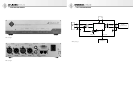
Fig. 3 shows a simple functional diagram of a mi-
crophone interface with an AES 42 input and an
AES/EBU output.
8.2 XLR cables
The length of cable that can be used from a digital
Neumann microphone to the DMI-2 is dependent
upon the type of cable and upon the sampling rate
(word clock frequency) selected. For cable lengths
of up to 100 m with a sampling rate of 44.1 kHz or
48 kHz, high-quality “analog” XLR 3 cable (e.g.
the IC 3 cable supplied by Neumann) can be used.
For greater cable lengths, the use of AES/EBU ca-
bles [110 ohms] is required. If AES/EBU cables are
employed, the following cable lengths can typi-
cally be used: Up to 300 m with a sampling rate of
44.1 kHz or 48 kHz; 200 m with a sampling rate of
88.2 kHz or 96 kHz; 100 m with a sampling rate of
176.4 kHz or 192 kHz.
Attention: If long cables are used to connect the
microphone with the DMI-2, the DC resistance of
the cables must not exceed a certain maximum
value, since an excessive DC resistance would re-
sult in an impermissible voltage drop in the phan-
tom power. The following formula applies:
Rc/2 + Rs < 18 ohms
Rc = DC resistance of the individual cable
core,
Rs = DC resistance of the shield or the GND
return line.
The length of cable that can be used from the DMI-2
to subsequent equipment (e.g. a digital mixing
console) is substantially dependent upon the
technical features of the subsequent equipment.
Thus no specifi c statements can be made concern-
ing the cable length. In case of doubt, the use of
AES/EBU cables [110 ohms] is recommended.
8.3 Operation without the RCS control software
All of the settings which are in eff ect when the
DMI-2 is switched off are stored internally, and
are automatically sent to the microphone when
the equipment is switched on again. The most
recent microphone settings are restored, without
requiring a connection to the control device (PC
or Mac).
The same procedure is followed if a microphone is
connected to the DMI-2 later, after the DMI-2 has
already been switched on.
When the RCS control software is started, the con-
fi gurations stored there for all of the microphone
channels are compared with the settings stored in
the DMI-2. If diff erences are detected, a menu is
displayed that asks which confi guration is to be
used (see RCS Operating Manual).