


12
US
GB
13
US
GB
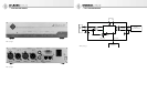
AES 42 In
This is a 3-pin XLR input for connecting a digital
microphone.
AES/EBU Out
This is a 3-pin XLR output for the AES/EBU output
signal. See the “XLR cables” section for permis-
sible maximum cable lengths depending upon the
selected sampling rate.
The AES/EBU signal includes 2 standard audio
channels (stereo left and right).
In the case of synchronous operation with two
mono microphones (see “Synchronization” sec-
tion), the audio data are distributed as follows be-
tween the audio channels of the AES/EBU output
signal:
Channel 1 AES/EBU Out
Left: Microphone 1
Right: Microphone 2
Channel 2 AES/EBU Out
Left: Microphone 2
Right: No signal
In all other cases, the following assignment ap-
plies:
Channel 1 AES/EBU Out
Left: Microphone 1
Right: No signal
Channel 2 AES/EBU Out
Left: Microphone 2
Right: No signal
Control Bus
RJ-45 ports are provided for connecting a control
device, which is generally a computer (PC or Mac).
Standard Ethernet (patch) cables are used as con-
necting cables: Shielded Twisted Pair (STP) or Un-
shielded Twisted Pair (UTP).
Data transfer is eff ected via an RS 485 interface
with an additional power-out pin, for the optional
supply of an external control device.
Attention: The RJ-45 ports of the DMI-2 must not
be connected to an Ethernet.
The two RJ-45 ports are connected in parallel, in
order to permit cascading and computer opera-
tion with multiple DMI devices.
The DMI-2 is connected to the USB port of a PC or
Mac. A USB/RS 485 converter is supplied for this
•
•
•
•
purpose. This permits use of the plug-and-play ca-
pability of available USB ports together with the
much longer cable lengths (at least 100 m) that
are possible with an RS 485 connection.
ID [device address]
The device address is set by means of a coding
switch on the back of the device. If multiple DMI
devices are cascaded and controlled together,
they must have diff erent device addresses (IDs).
The addresses that can be used are dependent
upon the RCS control software employed. Cur-
rently, only the addresses 0, 1, 2 and 3 are permit-
ted (see also Section 5, “Setup”).
Attention: The device address should be changed
when the DMI is not supplied with power, since
the new address will not take eff ect until the next
time the device is switched on.
Please see the RCS control software operating
manual for information concerning the mode of
operation and assignment of device addresses.
Attention: On the front of the device is an open-
ing labelled “ID”. Here there is a push-button for
various future functions, which will include a
convenient means of setting the device address.
However, at present this button is not yet opera-
tional.
User Port
This permits direct control of microphone func-
tions by means of external switch contacts or
logic signals.
The assignments of the 9 pins are as follows (low-
active):
Pin 1 Channel 1 “Light 2” off (red LED, currently
only for the D-01 Solution-D microphone)
Pin 2 Channel 1 “Light 1” off (blue LED of Solu-
tion-D microphones)
Pin 3 Channel 1 mute switched on
Pin 4 Reserved
Pin 5 Ground
Pin 6 Channel 2 “Light 2” off (red LED, currently
only for the D-01 Solution-D microphone)
Pin 7 Channel 2 “Light 1” off (blue LED of Solu-
tion-D microphones)
Pin 8 Channel 2 mute switched on
Pin 9 Reserved
The pins can be controlled via contact with
ground, or alternatively by means of logic outputs
(TTL logic level). For example, in the case of mut-
ing, the mute can be activated and the red LED
switched off via a single contact (e.g. for the “On
Air” function).
Attention: The respective switch function is ac-
tivated only when “User Port” has been selected
in the RCS control software for the control of the
relevant function.
4. Equipment supplied
DMI-2 Digital Microphone Interface
USB 485 converter
USB cable
RJ-45 cable
Power cable
Operating manual
CD with RCS software and USB driver
5. Setup
The following steps are to be carried out for the
initial installation of a digital microphone system
consisting of the microphone, the DMI-2 Digital
Microphone Interface, and the RCS control soft-
ware.
First install the RCS control software and the as-
sociated drivers on your computer.
The minimum requirements for operation of the
RCS control software on the computer are:
Computer with Windows 98 SE, ME, 2000 or
XP operating system, or Mac OS with PPC (ver-
sion 8.6 or higher, and CarbonLib version 1.6
or higher)
A free USB port
10 MB of free hard disk space
Graphics resolution of 1024 x 768 or more
HiColor or TrueColor
CD-ROM drive
Mouse and keyboard
Adobe Acrobat Reader (only for the online
manual)
Start the setup program on the accompanying
CD-ROM (Windows: “Setup”; Mac OS: “Install
RCS”) and follow the instructions displayed on
the screen.
•
•
•
•
•
•
•
•
•
•
•
•
•
•
•
Attention:
Administrator rights are required for installa-
tion with Windows 2000/XP or Mac OS X.
The USB 485 converter must not be attached to
a computer USB port until after the RCS soft-
ware has been installed.
USB driver installation
After the RCS has been installed, the USB 485
interface converter must be connected to a com-
puter USB port. This ensures loading of the sup-
plied USB driver, which is required for operation
of the converter. In the Windows operating sys-
tem, if there is a query regarding the storage loca-
tion of the driver fi les, the CD-ROM drive should
be selected. Before confi rmation, ensure that the
installation CD-ROM has been inserted into the
drive.
Other connections
Using a patch cable, connect the USB 485 con-
verter to one of the RJ-45 ports (control bus) of
the DMI-2.
Set the device address (ID) of the DMI-2 (using
the coding switch on the back of the DMI). Ad-
dresses should be assigned beginning with “0”.
The addresses 0 to 3 are currently supported by
the RCS.
Attention: The ID is detected only during startup
of the DMI-2. Therefore, switch the power supply
off and then back on again after changing the ID,
so that the change will be detected. (Refer to the
“ID” section, page 11)
Connect the microphone, the DMI-2 and the sub-
sequent device (e.g. mixing console) by means of
XLR cables (see “XLR cables” section).
If the DMI and the connected microphones are
to be synchronized with an external master word
clock, use a BNC cable to connect the master word
clock port to the Word Clock input of the DMI-2.
If multiple DMIs are used, they can be cascaded
via the control bus. For this purpose, use an RJ-
45 patch cable to connect the second RJ-45 port
of the initial DMI to one of the RJ-45 ports of the
second DMI, etc.
If necessary, also transfer the word clock signal to
additional DMIs, via the BNC output. Connect the
DMI-2 to the power supply network.
•
•