


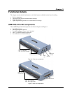

OMB-DAQ-2416-4AO User's Guide Functional Details
20
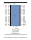
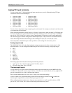
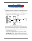
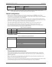
Figure 13. OMB-DAQ-2416-4AO data rate vs. resolution example
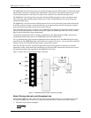
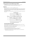
Input isolation
The OMB-DAQ-2416-4AO is an isolated data acquisition device. The analog I/O, digital I/O, counters, and all
the digital control/timing are referenced to an isolated ground as shown in the figure below. This ground is
physically and electrically separate from the ground use by the circuit connected to the system bus interface.
Isolation provides a barrier between the host PC and potentially hazardous voltages by physically and
electrically separating two parts of the measurement device.
The "non-isolated" ground is common to the chassis ground of the PC, while the "isolated" ground is not.
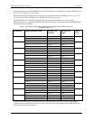
All analog measurements are made relative to the isolated ground. See Figure 14 for details.
Figure 14. OMB-DAQ-2416-4AO input isolation diagram
When making measurements in industrial environments, DAQ devices can encounter hazardous voltages,
transients, large common mode voltages and fluctuating ground potentials. Any one of these issues can
seriously degrade the measurement accuracy of the device and possibly damage the measurement instrument.
To overcome these issues, some DAQ devices provide physical and electrical isolation. Some of the benefits of
isolation include:
Safety: A DAQ device employing physical and electrical isolation helps to keep high voltages and
transients from damaging the system-side host PC.
Ground loops: Improper grounding of the signal source that the DAQ device is measuring is one of the
most common sources of noise and measurement inaccuracies. Isolation improves the measurement
accuracy by physically preventing ground loops. Ground loops—a common source of noise and error—are
the results of a measurement system having multiple grounds at different potentials.
Common mode rejection: With isolation, a DAQ device can measure small signals in the presence of
large common mode voltages. Isolation increases the measurement system's ability to reject common mode
voltages. The common mode voltage is the signal that is common to both the positive and negative inputs
of the measurement device, but is not part of the signal to measure.
640 µs delay before
next sample taken
Resolution = 20.6 bits
Resolution = 19.6 bits
Isolation
barrier
I/O connector
AIN/TIN
Aout
DIO
Counters
Isolated
µC
DSUB-37
connector
(OMB-AI-EXP32)
Digital
isolator
Non-
isolated
µC
USB
Non--isolated
ground
Isolated
ground