


OMB-DAQ-2416-4AO User's Guide Functional Details
22
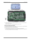
Figure 16. Location of screws connecting bottom and top sections of case
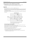
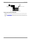
Figure 17. Location of JP1
4. To pull the digital pins down to ground, place the shorting block across pins 2 and 3 (refer to the jumper
orientation shown in Figure 17).
To pull the digital pins up to +5V, place the shorting block across pins 1 and 2.
External pull-up/pull-down capability
You can also place an external pull-up resistor on any of the DIO bits, which enables you to pull the DIO bit up
to a voltage that exceeds the internal +5 V pull-up voltage.
When using external pull-up resistors, be aware of the following:
You should either remove the JP1 jumper, or store it by attaching it to one of the three pins.
When using external pull-up resistors, the internal resistors cause slight impedance shifts to digital lines in
the "on" state as the number of lines in the "off" state changes.