


12
13
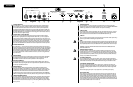
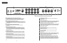
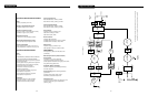
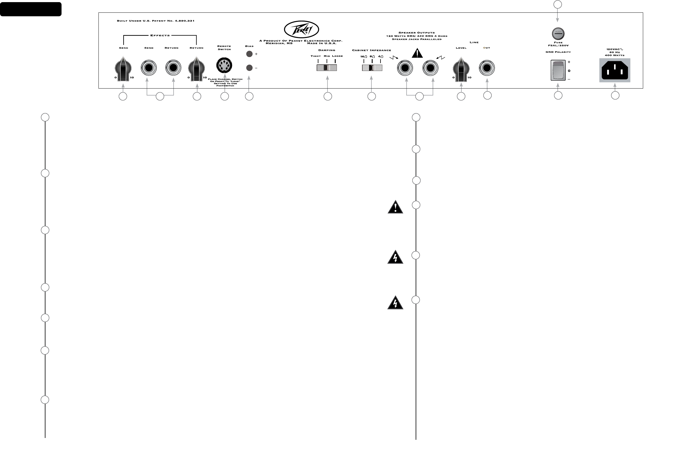
Rear Panel
1
2
3
4
5
6
7
EFFECTS SEND LEVEL
This calibrated (0 – 10) control sets the level of signal being sent to external effects
and/or signal processors. Clockwise rotation increases the amount of signal being
sent; counterclockwise rotation decreases the amount. For the quietest operation,
the EFFECTS SEND LEVEL should be set as high as possible. Generally, the SEND and
RETURN levels should be set oppositely. If the EFFECTS SEND LEVEL is set low, the EF-
FECTS RETURN LEVEL (19) is set high to achieve unity gain. If volume boost is desired,
turn both controls to higher settings.
EFFECTS SEND / EFFECTS RETURN
These 1/4” mono (TS) jacks allow signal to be sent to and returned from external
effects and/or signal processors. Using shielded cables with 1/4” mono (TS) phone
plugs, patch from EFFECTS SEND to the input of the external device, and from the out-
put of the external device to EFFECTS RETURN. Only devices that do not increase signal
gain should be used in this effects loop (chorus, delay, reverb, etc.). If the footswitch
is used, the EFFECTS SELECTOR (33) switch must be depressed to activate the effects
loop. See the FOOTSWITCH section of this manual for explanation of switch operation.
EFFECTS RETURN LEVEL
This calibrated (0 – 10) control sets the level of signal being returned from external ef-
fects and/or signal processors. Clockwise rotation increases the amount of signal being
returned; counterclockwise rotation decreases the amount. Again, SEND and RETURN
levels should be set oppositely, with the SEND level being high and the RETURN level
low to ensure the quietest operation. By setting both the Send and Return higher, you
can use the effects button on the footswitch as a boost if you aren’t using the effects
loop with effects.
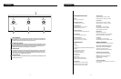
REMOTE SWITCH
This seven-pin DIN connector is provided for the connection of the remote footswitch.
The footswitch cable should be connected before the amp is powered up. See the
FOOTSWITCH section of this manual for explanation of switch operation.
BIAS TEST TERMINALS
These terminals are provided to measure the bias of the amplier’s power tubes. A
knob behind the back panel grille allows for adjustment. Bias adjustment should only
be done by a qualied technician.
DAMPING SWITCH
This three-position switch allows adjustment of the amplier’s damping factor.
Damping is the ability of an amplier to control speaker cone motion after a signal
disappears. A high damping factor (TIGHT) reduces cone vibration quicker than a low
(LOOSE) factor. This switch works much like the Resonance and Presence controls
on other Peavey amps, if those controls were turned simultaneously. If the DAMPING
SWITCH is changed, the volume of the amp will also change and require re-adjustment.
CABINET IMPEDANCE SWITCH
This three-position switch allows appropriate selection of speaker cabinet impedance.
If two enclosures of equal impedance are used, the switch should be set to half the
individual value. For example, two 16-ohm enclosures necessitate an 8-Ohm setting,
while two 8-ohm enclosures would require a 4-ohm setting. Minimum speaker imped-
ance is 4 ohms.
1 3 4 652
8
9
10
11
12
13
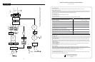
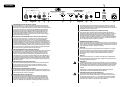
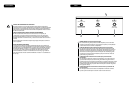
SPEAKER OUTPUTS
These paralleled 1/4” mono (TS) jacks are provided for the connection of speaker
enclosure(s). Again, minimum speaker impedance is 4 ohms. The CABINET IMPEDANCE
SWITCH (23) should be set to match the load of the speaker cabinet(s).
LINE OUT LEVEL
This control sets the level of signal being sent out of the LINE OUT (26) jack. It may be
used to balance the level of slave power amp/speaker systems driven from the LINE
OUT (26) to the level of cabinets driven from the SPEAKER OUTPUTS (24).
LINE OUT
This 1/4” mono (TS) jack provides a pre-power amp signal to drive another power amp/
speaker system while maintaining the amplier’s tone.
FUSE
A fuse is located within the cap of the fuse holder. This fuse must be replaced with one of
the same type and value to avoid damaging the amplier and voiding the warranty. If the
amp repeatedly blows the fuse, it should be taken to a qualied service center for repair.
WARNING: THE FUSE SHOULD ONLY BE REPLACED AFTER THE POWER CORD HAS
BEEN DISCONNECTED.
GROUND POLARITY SWITCH
This three-position, rocker-type switch should normally be placed in the center (0)
position. If hum or noise is noticed coming from the speaker enclosure(s), the switch
may be placed in the “+” or “-” position to minimize hum/noise. If changing the polar-
ity does not alleviate the problem, consult your authorized Peavey dealer, the Peavey
factory, or a qualied service technician.
IEC MAINS CONNECTOR
This is a standard IEC power connector. An AC mains cord having the appropriate AC
plug and ratings for the intended operating voltage is included in the carton. The mains
cord should be connected to the amplier before connecting to a suitable AC outlet.
U.S DOMESTIC AC MAINS CORD
The mains cord supplied with the unit is a heavy-duty, 3-conductor type with a con-
ventional 120 VAC plug with ground pin. If the outlet used does not have a ground pin,
a suitable grounding adapter should be used, and the third wire should be grounded
properly.
Never break off the ground pin on any equipment. It is provided for your safety.
NOTE: FOR UK ONLY
If the colors of the wires in the mains lead of this unit do not correspond with the col-
ored markings identifying the terminals in your plug, proceed as follows: (1) The wire
that is colored green and yellow must be connected to the terminal that is marked by
the letter E, the earth symbol, colored green, or colored green and yellow. (2) The wire
that is colored blue must be connected to the terminal that is marked with the letter N
or the color black. (3) The wire that is colored brown must be connected to the terminal
that is marked with the letter L or the color red.
7
11
10 12 13
8 9