


Pelco Manual C527M-L (3/04) [ 15 ]
INSTALLATION – CM6700 ASCII MODE
One ASCII keyboard can be installed, using either an RS-232 or RS-422 interface. If additional local and
remote keyboards are used, you should install them according to the instructions in the
Installation –
CM6700 Mode and Installation – CM6800 Mode
sections before doing an ASCII installation.
For installation at a remote location that is served by an RS-232 communications facility (such as via dial-
up phone lines), use an RS-232 connection at both the KBD keyboard and the matrix switcher. (Refer to
the
RS-232 Interface
section below.)
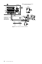
For installation at a remote location that is served by an RS-422 communications facility (such as direct-wire
or fiber-optic terminals), use an RS-422 connection at both the KBD keyboard and the matrix switcher.
(Refer to the
RS-422 Interface
section.)
NOTE: A KBDKIT or KBDKIT-X is required to use the keyboard in ASCII Mode. The KBDKIT consists of
two RJ-45 wall blocks and a 120 VAC to 12 VAC transformer. The KBDKIT-X is for 230 VAC.
Use one wall block.
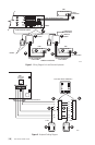
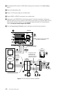
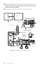
RS-232 Interface (CM6700)
An RS-232/RS-422 converter and power supply (Pelco part number PV130) are required. They are not in-
cluded and must be ordered separately.
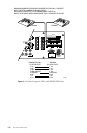
Refer to Figure 5.
ᕡ Remove the cover from the CM6700 SCU and verify that the DIP switches for COM 2 are set forRS-
232. Refer to the
COM 2 Port
section in the CM6700 Installation/Operation Manual for setting the
switches. Reinstall the cover.
ᕢ Use an existing CM6700 keyboard to program the COM 2 communication port. (If there is no other
keyboard, use the one you are installing. Set all DIP switches OFF and plug the keyboard into the
Local Keyboard port on the back of the CM6700. Remove when programming is completed.) Refer to
the
Setting COM 2 Communication Parameters
section in the CM6700 Installation/Operation Manual
for programming instructions. Set COM 2 port parameters as follows:
Baud: 9600, Parity: Odd, Stop Bits: 1
ᕣ At the CM6700 SCU, connect the COM 2 RS-232 port to the output of the RS-232 device at the SCU
side of the transmission link.
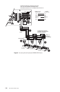
ᕤ Decide on a suitable location for the keyboard and wall block. The keyboard must be within 25 feet
(7.6 m) of the wall block. The wall block must be within 6 feet (1.8 m) of the nearest suitable electri-
cal outlet. Do not mount the wall block at this time.
ᕥ Remove the wall block cover and make connections between the wall block and the RS-232/RS-422
converter.
ᕦ Wire the +12 VDC power supply to the converter.
ᕧ Connect the RS-232 side of the converter to an RS-232 device that interfaces the transport network.
ᕨ At the wall block wire the transformer to pins 3 and 4. Polarity is unimportant.
ᕩ Replace the cover on the wall block. A double-sided sticky pad is provided to mount the wall block.
Secure the wall block to a suitable surface.