


[ 16 ] Pelco Manual C527M-L (3/04)
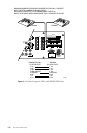
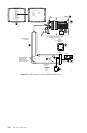
ᕫᕾ Set the keyboard DIP switches for ASCII Mode according to the instructions in the Switch Settings
section.
ᕫᕵ Plug in the keyboard data cable.
ᕫᕶ Plug the +12 VDC power supply into a suitable outlet.
ᕫᕷ Plug the KBDKIT or KBDKIT-X transformer into a suitable outlet.
ᕫᕸ Apply power to the CM6700 SCU (if not already powered). To initialize the keyboard, wait five sec-
onds after power-up, enter the number for the monitor you are viewing (1-4), and press MON. The LED
display shows the number entered. You can now use the keyboard to perform all normal keyboard
functions except you cannot program the CM6700.
ᕫᕹ Go to the Programming and Operation section and program and test for proper operation.
LOCAL
KEYBOARD
1
2
3
4
5
6
7
8
12 VAC
KBDKIT
RJ-45 WALL BLOCK
TERMINALS
RS-232
RS-422
CM6700SCU
RS-232 DEVICE
RS-232 DEVICE
PV130
RS-232/RS-422
CONVERTER
RD (B)
RD (A)
TD (A)
TD (B)
TX+
TX-
TERMINAL
RX-
RX+
POWER
SUPPLY
+12 VDC GND
9-PIN, MALE
CONNECTOR
ON CONVERTER
CUSTOMER SUPPLIED WIRING.
50 FEET MAXIMUM DISTANCE.
MAXIMUM DISTANCE
OF 4,000 FEET. USE
SHIELDED TWISTED
PA IRS SUCH AS BELDEN
9843 OR EQUIVALENT.
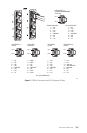
SCU COM 2
PIN
7 (TX+)
9 (GND)
12 (RX+)
12
6
7
13
5
8
RS-232
CUSTOMER SUPPLIED WIRING.
50 FEET MAXIMUM DISTANCE.
3
KBD300A
4
25-FOOT
KEYBOARD
DATA CABLE
101
WALL BLOCK
1
2
3
14
POWER UP
SCU
9
REPLACE
COVER
11
SET SWITCHES
DB9 PINS
3(TX+)
2(RX+)
5(GND)
ANY RS-232 NETWORK
TRANSPORT
NETWORK
1
2
3
45
6
7
8
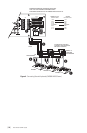
NOTE: A SEPARATE PATH MUST BE PROVIDED
FOR VIDEO TO THE MONITOR.
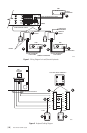
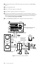
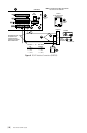
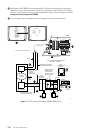
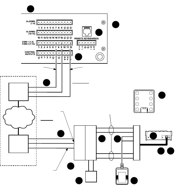
Figure 5. RS-232 Interface Connections (CM6700)