


DRB1474-A
En
27
Changing the settings
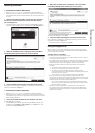
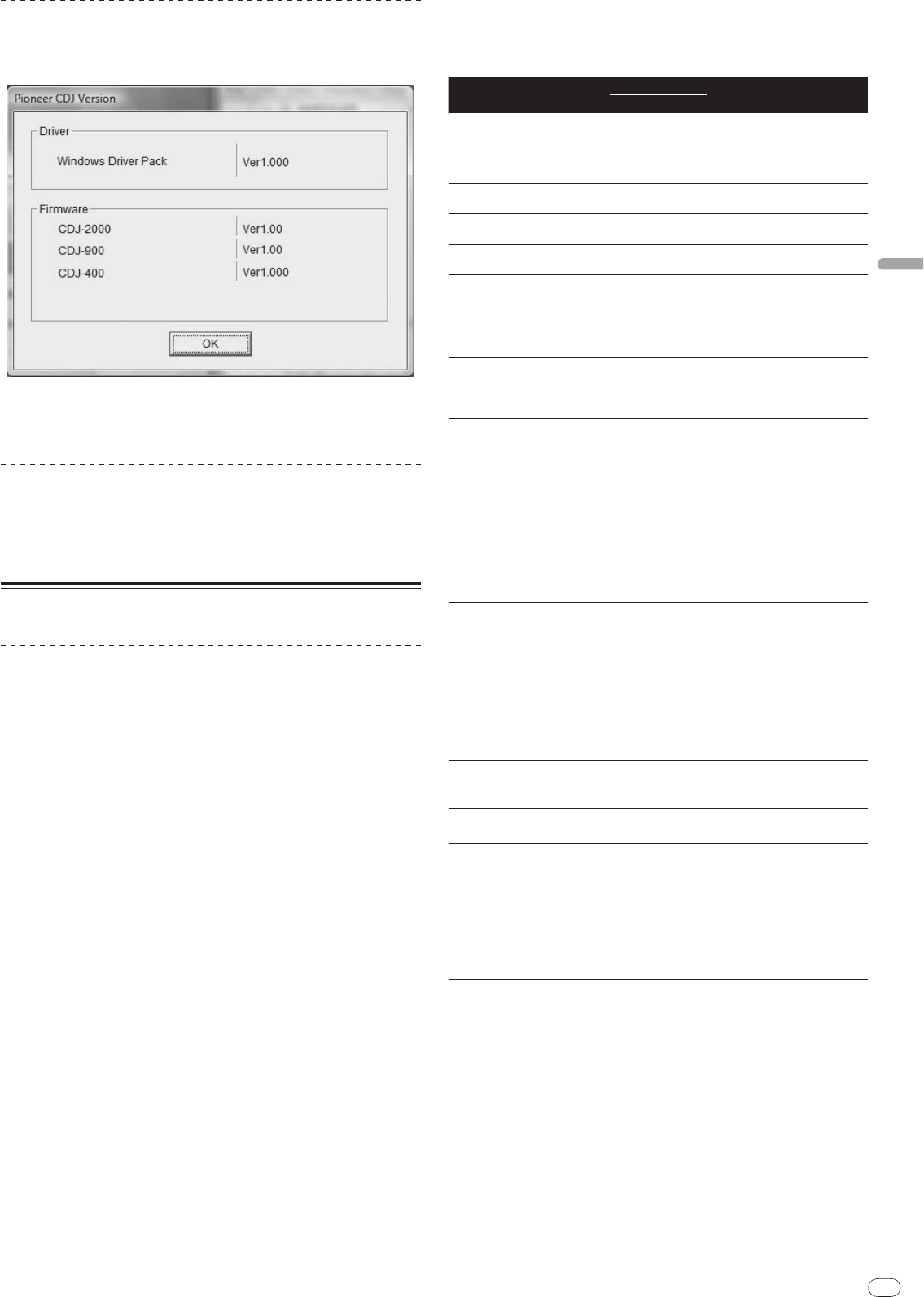
Checking the version of the driver software
Click Windows [Start] menu >[All Programs]>[Pioneer]>[Pioneer
CDJ]>[Pioneer CDJ Version Display Utility].
You can check the firmware version of this unit on the screen.
The firmware version is not displayed when the CDJ-2000 is not connected
to the computer or when the CDJ-2000 and computer are not properly
communicating.
Checking the latest information on the driver
software
For the latest information on the driver software for exclusive use with this unit,
visit our website shown below.
http://www.prodjnet.com/support/
Using other brands of DJ software
Operating DJ software by MIDI interface
The CDJ-2000 also outputs the operating data for the buttons and dials in MIDI
format. If you connect a computer with a built-in MIDI-compatible DJ software
via a USB cable, you can operate the DJ software on this unit. The sound of
music files being played on the computer can also be output from the CDJ-2000.
Before using the CDJ-2000 as an audio device, install the driver software on the
computer (page 26). Also, the CDJ-2000 must be selected in the DJ software’s
settings. For details, see your DJ software’s operating instructions.
1 Connect the USB port on this unit to your computer.
For instructions on connecting, see Using other brands of DJ software on page 13.
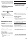
2 Press [BROWSE], then press [LINK].
[Control Mode] and [USB-MIDI] appear on the menu screen.
3 Select [Control Mode] and enter.
The connecting screen is displayed.
4 Select [USB-MIDI] and enter.
The CDJ-2000 switches to the control mode.
5 Start the DJ software.
Communication with the DJ software starts.
The DJ software on the computer can be operated using the buttons and
rotary selector on the CDJ-2000.
It may not be possible to use some buttons to operate the DJ software.
The control mode is canceled when a track is loaded in the CDJ-2000.
For messages output by the CDJ-2000, see List of MIDI Messages.
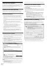
Changing the MIDI channel setting
1 Press [MENU/UTILITY] for over 1 second.
The utility screen appears.
2 Select [MIDI CHANNEL] and enter.
3 Turn the rotary selector.
Select the MIDI channel and change the setting. A setting from 1 – 16 can be
selected.
4 Press the rotary selector to enter.
5 Press [MENU/UTILITY].
The previous screen reappears.
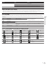
List of MIDI Messages
SW Name SW Type
MIDI Messages
Notes
MSB
JOG (TOUCH)
-
Bn 10 dd
A linear value corresponding to
the speed, from stop to 4X: 64 for
stop, 65 (0.06X) – 127 (4X) in the
forward direction, 63 (0.06X) – 0
(4X) in the reverse direction.
TEMPO SLIDER VR Bn 1D dd
0 – 127, 0 on the – side, 127 on
the + side
TOUCH/
BRAKE VR Bn 1E dd
0 – 127, 0 (min.) on the left side,
127 (max.) on the right side
RELEASE/
START VR Bn 1F dd
0 – 127, 0 (min.) on the left side,
127 (max.) on the right side
JOG RING
-
Bn 30 dd
A linear value corresponding
to the speed from 0.5X to 4X: 64
when stopped (under 0.49X), 65
(0.5X) to 127 (4X) in the forward
direction, 63 (0.5X) to 0 (4X) in the
reverse direction.
ENCODER
General
Purpose
Controller
Bn 4F dd
98 – 127, 1 – 30 Difference of count
from previous time is sent (±1 –
±30) When over ±30, set at ±30
PLAY/
PAUSE SW 9n 00 dd OFF=0, ON=127
CUE SW 9n 01 dd OFF=0, ON=127
SEARCH FWD SW 9n 02 dd OFF=0, ON=127
SEARCH REV SW 9n 03 dd OFF=0, ON=127
TRACK SEARCH
NEXT
SW 9n 04 dd OFF=0, ON=127
TRACK SEARCH
REV
SW 9n 05 dd OFF=0, ON=127
LOOP IN SW 9n 06 dd OFF=0, ON=127
LOOP OUT SW 9n 07 dd OFF=0, ON=127
RELOOP SW 9n 08 dd OFF=0, ON=127
MEMORY SW 9n 0A dd OFF=0, ON=127
CALL NEXT SW 9n 0B dd OFF=0, ON=127
CALL PREV SW 9n 0C dd OFF=0, ON=127
DELETE SW 9n 0D dd OFF=0, ON=127
TIME/
A.CUE SW 9n 0E dd OFF=0, ON=127
TEMPO RANGE SW 9n 10 dd OFF=0, ON=127
MASTER TEMPO SW 9n 11 dd OFF=0, ON=127
JOG MODE SW 9n 12 dd OFF=0, ON=127
HOT CUE A SW 9n 18 dd OFF=0, ON=127
HOT CUE B SW 9n 19 dd OFF=0, ON=127
HOT CUE C SW 9n 1A dd OFF=0, ON=127
HOT CUE REC/
CALL
SW 9n 1C dd OFF=0, ON=127
TEMPO RESET SW 9n 1D dd OFF=0, ON=127
JOG TOUCH SW 9n 20 dd OFF=0, ON=127
REVERSE SW 9n 21 dd OFF=0, ON=127
4 BEAT LOOP
-
9n 2A dd OFF=0, ON=127
EJECT SW 9n 2F dd OFF=0, ON=127
TAG TRACK SW 9n 30 dd OFF=0, ON=127
BACK SW 9n 32 dd OFF=0, ON=127
ENCODER PUSH SW 9n 33 dd OFF=0, ON=127
NEEDLE
Touch Sensor
Bn 1C dd
OFF = 0 1 to 127 position data
from left to right side
n is the channel number.