


- 8 -
5
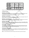
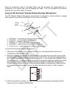
Sharing Mode
Not Sharing: all
frequencies will
be used
Sharing: ½
frequencies will
be used
6
A/B
Frequencies
A Frequencies
B Frequencies
150'
100'
30'
15'
7
Transmit
Power
Off
On
Off
On
8
Off
Off
On
On
Changes in DIP switch configurations require a power cycle (off/on) to take effect.
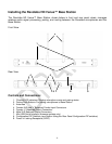
Configuration Settings
DIP Switch 1- Output Mixing:
When DIP Switch 1 is OFF(default), each HD microphone has its own 3.5mm balanced audio output
on the Base Station. When DIP Switch 1 is switched on, the audio outputs of the two HD
microphones are mixed together and sent to both outputs.
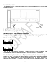
DIP Switch 2 - Low Pass Filter:
When DIP switch 2 is OFF(default) the microphone provides the full audio bandwidth. When DIP
switch 3 is ON, a LPF is activated reducing the audio bandwidth.
DIP Switch 3 – Audio Output Level:
When DIP switch 3 is OFF(default) the microphone outputs provide a line level signal~0 dBu. When
DIP switch 3 is ON, the microphone outputs provide a mic level signal ~-40 dBu.
DIP Switch 4 - Mute Mode:
When DIP switch 4 is OFF(default) each microphone has its own individual muting capabilities. When
DIP switch 4 is ON, the microphone mute buttons are deactivated resulting in the mics always being
active and un-muted when not in the Charger Base.
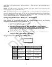
DIP Switch 5&6 – Sharing Mode:
To use two HD Venue Systems in the same area, both systems must have DIP Switch 5 set to ON.
One of the HD Venue Systems must have DIP Switch 6 set to ON (A frequencies) and the other HD
Venue System must have DIP Switch 6 set to OFF (B frequencies).
DIP Switch 7&8 - Transmit Power:
The transmit power of the Base Station can be adjusted to help reduce the operational radius of a
Revolabs HD Venue System in order to prevent interference from other Revolabs products, or from
other devices operating in the same frequency.
Note: It is recommended that the lowest functioning Transmit Power be used for each system.