


Using the MV8-OP1
9
MV-8800 Using the MV8-OP1
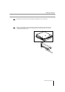
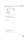
If the MV-8800 is connected to another device that has an R-BUS connector, you can use two channels of
digital audio input and eight channels of digital audio output.
●
You may connect only another R-BUS device to the R-BUS connector. Even if the connector has the same
shape, you must never attempt to connect a SCSI, RS-232C, or parallel interface. Doing so will cause
malfunctions.
●
Use an R-BUS cable (RBC-1 or RBC-3: each sold separately) to make connections to an R-BUS connector.
●
Before connecting or disconnecting the R-BUS cable, you must turn off the power of the MV-8800 and the
other R-BUS device. If you make connections while the power is on, the system may fail to operate correctly,
and malfunctions may also occur.
●
R-BUS is the same specification as “RMDB2” and “RMDB II.” It can be used without any problems with
devices marked “RMDB2” or “RMDB II.”
●
R-BUS is not compatible with “RMDB”.
●
The RBC-5 (5 meter R-BUS cable: no longer available) cannot be used with the MV-8800. Please use the
RBC-1 (1 meter R-BUS cable) or RBC-3 (3 meter R-BUS cable).
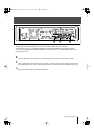
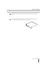
Here’s how to specify whether the word clock master device (the device that produces the synchronization
signal that regulates transmission and reception of digital audio signals) will be the MV-8800 itself or the
external device connected to the R-BUS connector.
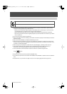
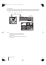
1.
Press [SYSTEM].
The SYSTEM MENU screen (Screen Guide; p. 172) will appear.
2.
With the cursor located in the upper row of icons, press [F2](R-BUS). Alternatively, select
the R-BUS icon and press [ENTER].
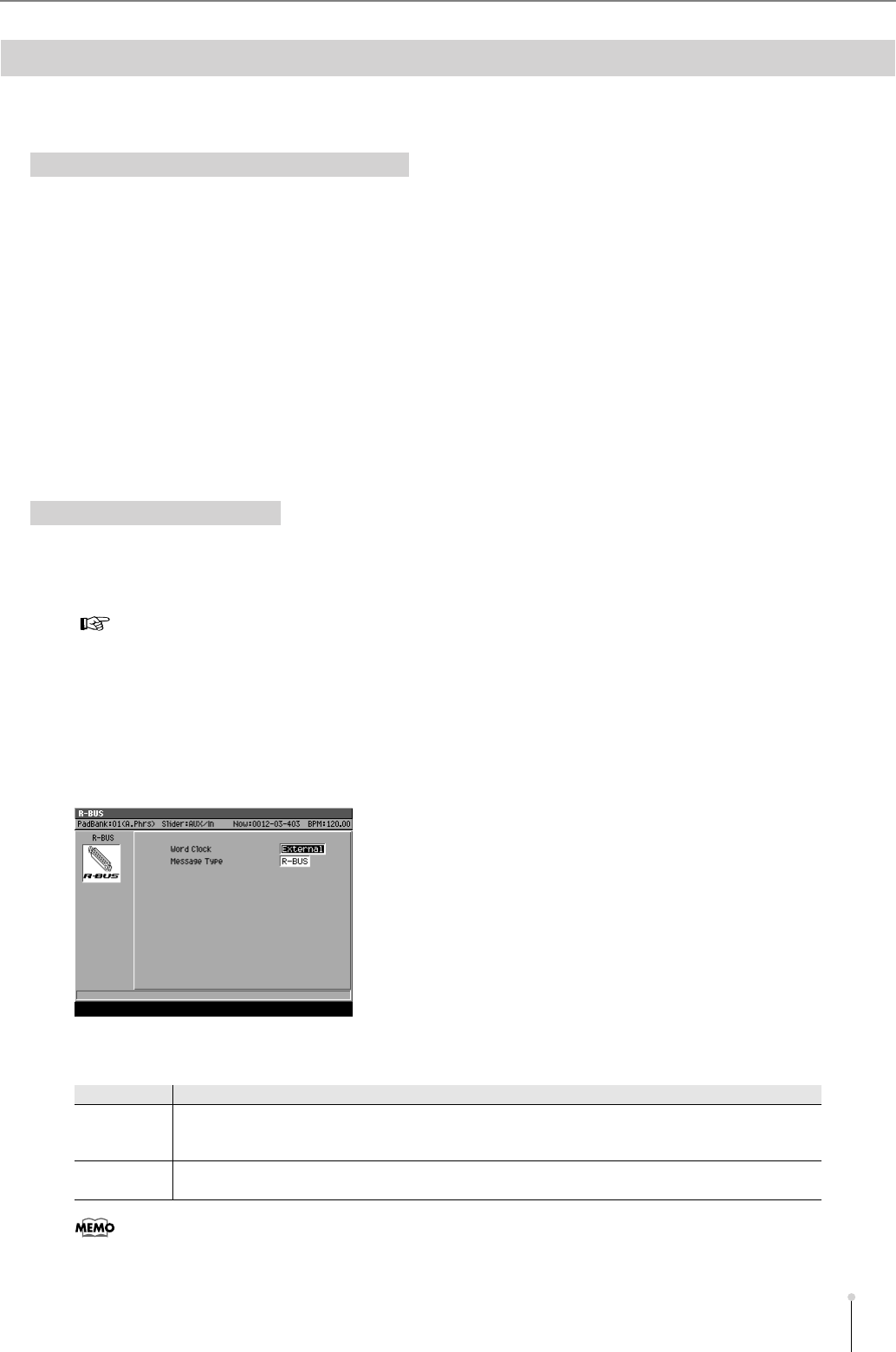
The R-BUS screen (Screen Guide; p. 183) will appear.
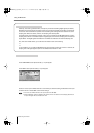
3.
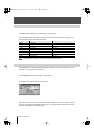
Set the Word Clock parameter.
Normally, you should use the “External” setting.
Transferring digital audio via R-BUS
Caution when connecting an R-BUS device
Making word clock settings
●
For details on word clock, refer to “Digital Connection with the Word Clock” (p. 10).
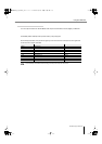
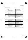
Value
Explanation
External
The word clock will be received from an externally connected R-BUS device. In this case, the sampling
rate of the signal sent from the MV8-OP1’s R-BUS connector will match the sampling rate of the external
R-BUS device.
Internal The word clock (44.1 kHz) will be generated inside the MV-8800, and transmitted via the R-BUS
connector. Set the external R-BUS device connected to the R-BUS connector to operate as the Slave.
●
The signal transmitted from the MV-8800’s OUTPUT DIGITAL and the internal processing of the sampling
functionality and the like is always 44.1 kHz.
MV-8800_b_MV8OP1_e.fm 9ページ 2006年12月6日 水曜日 午後1時11分