


5
ENGLISH
5
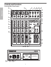
Front and Rear Panel Layout
FRONT PANEL
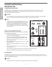
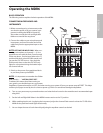
1 MIC/LINE – Combination Input connector for Low-Noise
Microphone pre-amp and Line level inputs.
2 GAIN – Used to set the input level of the mic pre and line
input.
3 CLIP – Red LED will illuminate indicating when the mic GAIN
has been adjusted too high.
4 HIGH FREQUENCY – Controls the high band of the Channel
Equalizer, +/- 15 dB at 12KHz.
5 MID FREQUENCY – Controls the mid band of the Channel
Equalizer, +/- 15 dB at 2.5KHz.
6 LOW FREQUENCY – Controls the low band of the Channel
Equalizer, +/- 15 dB at 80Hz.
7 AUX – Pre fader auxiliary send that can be used with an exter
-
nal effects processor, or to create a cue or monitor mix.
8 PAN – Controls the channel’s position between left and right
in the stereo bus.
9 RECORD – Used in the HDM (HARD DISK MODE) to assign the
channel to the Record bus.
10 FADER – 60 mm audio taper fader provides smooth control
over level changes.
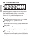
11 STEREO MIC/LINE - Combination Input connector for
Low-Noise Microphone pre-amp and Left Line Input for the
stereo channels.
12 RIGHT LINE – Right Line Input connector on the stereo chan
-
nels.
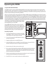
13 AUX RET – Input connector from external line level sources.
14 CONTROL ROOM – Left and Right output connectors for con
-
necting a monitor system.
15 MIX – Left and Right main Mix output connectors.
16 AUX OUT – Line level output from the Auxiliary bus.
17 MONO OUT – The Left and Right main Mix outputs are
summed together to a monaural signal and sent out this con
-
nector.
18 2 TRACK INPUTS & OUTPUTS – Connect a DAT,
Cassette, Mini Disk or Hard Disk Recording system.
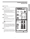
19 MONO OUT LEVEL – Used to set the volume of the
MONO mix.
20 HDM ( Hard Disk Mode) - Switch configures the mixer for
recording and overdubbing on a computer based hard
disk recording system.
21 PHANTOM – Indicates that the 48 Volt Phantom Power is
on.
22 POWER – Indicates the MDR6 is powered up.
23 OUTPUT METER - Five segment display with VU
ballistics indicates main Mix level.
24 MIX FADERS – Used to control the overall volume of
the Left and Right main Mix outputs.
25 2TK LEVEL - Level control used to mix the 2 track input
with the mix from the channel inputs.
26 AUX RETURN – Used to mix in level of the effects return.
27 HEADPHONE JACK – Connect stereo headphones here.
28 C ROOM/HEADPHONE – Adjusts the volume of the con
-
trol speakers or headphones.
29 2TRACK/MIX – Switches between the main Mix and the
2 Track in the Control Room output.
30 BALANCE – Adjusts the relative loudness of the
signal sent to the Left and Right mix outputs.
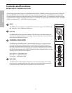
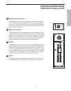
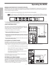
REAR PANEL
A AC ADAPTOR INLET – Connect External AC power sup-
ply here.
B POWER – Switches on the MDR6’s main power.
C PHANTOM – Engages the 48-Volt Phantom power sup
-
ply to microphone pre- amps.
Front and Rear Panel Layout