


B. Setting up and operation
1. Transmitter SK 1006
The battery compartment of the transmitter becomes accessible by taking
off the base plate. After the coin nick locking screw has been turned to the
left, the base plate can be lifted by a finger nail grasping into the lateral
slol. The connection plate for the batteries with in four press-stud contacts
is rigidly fixed to the base plate. After inserting of the batteries - which is
only possible when correctly poled - the base plate including the batteries
is replaced into the unit and locked.
The microphone plug is connected to the 6-pole socket (B)of the transmitter,
and the Transmitter is switched on by means of the sliding switch (5) towards
the mark "Ein". Using the microphone MD 405 S, the supply current can
additionally be switched on or off by means of the microphone switch.
When the microphone plug is disconnected from the transmitter socket, no
current is supplied to the transmitter, and no battery wastage will result
from accidental switching-on of the unit. (JII. on page 4).
For adjustment of the frequency deviation (audio frequency gain) the ad-
justing control (R) can be operated from outside. The adjusted ga in can be
read at the opening (F) and is marked by the numbers 1 . . .6. Levelling
of the transmitter has to be carried out with the receiver ready for use and
in conjunction with a person speaking.
Normally the frequency is set to 36.7 megacps in the factory. By means of
a clearly marked turning switch situated in the battery compartment end to
be operated with a screw-driver, it can be changed to 36.7 megacps. Care
should be taken to ensure that the switch has been turned right over to its
final position.
The screening of the microphone cable is used as aerial for the transmitter.
It should be as vertical and stright as possible to provide the greatest
possible aerial heighl.
The transmitter is carefully adjusted and sealed in the factory. It is recom-
manded to have eventual repairs executed by the competent supplier in
order to ensure that official regulations concerning the technical data of
the unit will be complied with.
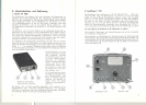
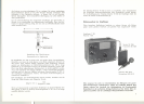
The following connecting-, operating-, and monitoring devices are located
on the front panel of the receiver (JII. on page 5):
Aerial connection and locking socket for the telescopic aerial (1), audio
frequency lead connection (2), diversity lead connection (3), remote control
lead connection for tape recorders (4), mains switch and volume control
for the monitoring loudspeaker (5), pilot lamp (6), frequency selector switch
(7), monitoring loudspeaker (8), and control for the electronic noise sup-
pression (9).
The aerial to be used has to be erected vertically at a suitable place
within the transmission range of the transmitter. The aerial lead has to be
conneded to the socket (1). The power amplifier must be connected to the
socket (2) by means of the standard miniature plug (e. g. Preh 5991 or
Hirschmann Mas 3). The socket (2) is wired as foliows:
contact 1 and 3 . . . . . .. audio frequency
contact 2 . . . . . .. case of the receiver.
As the receiver is connected to the ground through the protective pin of
the mains plug, it is necessary to play attention when connecting the ampli-
fier to avoid ground loops. The shield of the connection cable has to be
led to the earth contact of the amplifier irrespective of whether its input
is balanced or unbalanced. At the receiver the shield is not to be connected
to contact 2.
2. Receiver T 201
The receiver can be operated by choice from a. c. mains of 110, 127, 220,
240 volts and 50...60 cps. For 40 cps mains supply the receiver can be
delivered with a special mains transformer. The mains cable is fixed to
the unit and is fitted with a protective pin plug. In the factory the receiver
is set to 220 volts operation. If it is to be operated from another voltage
the voltage selector must be adjusted. This can be done after opening the
case by loosening 4 safety screws. The 0.3 amp. fuse must be replaced
by a 0.6 amp. fuse when switching over to operation on 110/127 volts.
Caution! Be sure to disconnect the plug from the mains supply before
opening the case.
Abroad it may be required to replace the plug with protective pin by a
standard plug (this is not admitted in Germany according to the VDE
regulations). In this case the housing of the receiver has to be connected
either through aseparate cable to the earth or through the shield of the
cable to the ground connection of the amplifier. In this case the shield has
to be connected to contact 2 of the miniature plug.
Several receivers can be connected for diversity operation. As it is impro-
bable that minimum values of field intensity are found simultaneously at
two different places, it is obvious to locate the aerials of the receivers
spatially distributed. The receivers are to be connected in parallel by means
of the cables for diversity operation at the sockets (3). Thus the following
units are fed by those receivers, the aerial voltage of which is sufficiently
high.
The socket "Tonband stop" (4) is provided for additional connection of a
tape recorder, the tape driving mechanism of which can be remote con-
trolled in this way by the transmitter to reduce the tape consumption. This,
however, requires that the tape recorder is fitted with a remote control
connection. The tape recorder is running as long as the transmitter is
in action. Warning and signal devices can be remotely controlled in this
manner, too.
The cable type TV 201 available as accessory part can be used as weil
for diversity operation as for tape recorder remote contro!.
16
17