


The Mikroport wireless microphone system
As Mikroport is a portable radio system, in many countries special licens-
ing regulations for operating the system have to be observed. In the
Bundesrepublik Deutschland the notification to the "Deutsche Bundespost"
is required. For this purpose a form of application attached to the instruc-
tion manual has to be filled in and sent to the competent local Oberpost-
direktion.
Therewith all formalities are fulfilled.
to the required power level for transmission. The operating voltage of the
transmitter is electronically stabilized. The transmitter has two channels of
equal performance normally with frequencies of 36.7 and 37.1 megacps
alternatively to be selected by a switch.
Note: In the Bundesrepublik Deutschland solely the two transmission
frequencies of 36,7 and 37.1 megacps are licensed by the Deutsche Bundes-
post. For use abroad and in case of a fixed order however the channels
can be adjusted to two other frequencies in the range between 25 and
45 megacps. The frequency interval mayamount from 0.3 megacps minimum
to 1 megacps maximum. This readjustment can be performed exclusively
by the manufacturer. Subsequently the receiver has to be provided for these
frequencies, too, which requires a corresponding modification.
III1
A. Description and mode of operation
1. Microphones
The microphones specially developed for the Mikraport equipment, i. e. the
hand microphone MD 405 S, as standard type, and the very small and
unobservable types "fountain-pen microphone" MM 61/2 and "button-hole
microphone" MM 23/2 that are meant for the transmission of speech only,
must not be replaced by other microphones in Germany with regard to
postal regulations. Other types for special purposes can however be
delivered on request.
The dynamic hand microphone MD 405 S with cardioid characteristic is
equipped with an on/off sliding switch for the transmitter. The magnetic
microphones MM 61/2 and MM 23/2 with omni-directional characteristic,
however, have no switch due to their tiny dimensions.
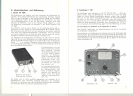
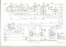
3. Receiver T 201
The illustration on page 1 shows the circuit of the different microphones.
When the microphone switch shall have the funktion of a muting button, the
free core in the microphone switch is to be soldered on to contact 4, and
a bridge is to be made between contact 1 and contact 2. The transmitter can
then no Ionger be switched on or off by the microphone switch.
The receiver contains an input- and mixer-stage, a two-stage intermediate
frequency section, a ratio detector, a two-stage audio frequency section,
and a two-stage direct-coupled amplifier for electronic noise suppression.
The input stage is equipped with the pentode EF 184 with reinforced grid
and extraordinary slope. This grants best sensitivity and minimum noise
level. The receiver can be switched to two operating frequencies selec-
tively. An automatic resetting section equipped with the silicon diode BA 100
serves for exact tuning to the respective transmission frequency.
The intermediate frequency section delivers a constant output voltage to
the ratio detector when the radio frequency voltage at the aerial input
exceeds a threshold value of 5 microvolts. By that means the audio frequency
output voltage remains constant, too. When the adjusted value of the aerial
voltage falls below (2 microvolts... 10mvolts), the electronic noise sup-
pression stage cuts off the units connected to the output of the receiver.
The audio frequency voltage is obtained from the cathode circuit of an
impedance converter stage earthfree and balanced by means of a coupling
transformer. The output level of + 6 dB (1.55 volts) corresponds to the
value normally used in public adress techniques. Because of the low source
impedance of 30 ohms any normal control or amplifier may be connected
to the output of the receiver. The audio monitoring of the performance can
be carried out by means of the built-in controllable monitoring loudspeaker
which remains in operation also when the electronic noise suppression stage
has cut off the public adress system.
Occasionally performances in rooms may be disturbed even within the
transmission range of the transmitter as a result of minimum values of
field intensity caused by unfavourable conditions. To avoid these distur-
bances it was provided to assemble two or more receivers for diversity
operation. By that the Mikroport system is outstanding by its good reliabi-
lity of operation and immunity from interferences even at disadvantageous
conditions.
By means of the built-in automatic switching device moreover a tape
recorder can be switched on or off via the transmitter.
2. Miniature transmitter SK 1006
1111,
I
This transmitter is built up with a printed circuit. Being fully transistorized,
it requires only two commercial batteries for feeding, which have a life of
approx. 6 to 7 hours of operation.
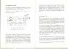
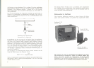
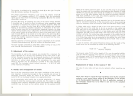
The unit consists of a three-stage modulation amplifier and a three-stage
HF transmitter. The function of the individual stages is shown in the block
diagram on page 2.
The audio frequency from the micraphone is amplified, then preemphasized
and applied to the gain contral (frequency deviation adjustment). The
two following amplifier stages are equipped with an automatic gain control
(dynamic compressionJ, so that the frequency deviation of the transmitter is
limited to a maximum of :t 75 kc/s. The modulation is achieved directly in
the transistor oscillator. To ensure good frequency stability of the transmitter,
the oscillator frequency is doubled to the output frequency, then amplified
14 15
II~I