


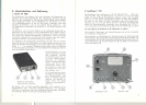
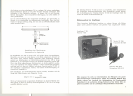

The receiver is switched on by rototing the knob (5) to the right. The pilot
lamp (6) indicates readiness for operation.
The chosen transmission frequency is set up by the selector switch (7)
(position 1 : 36.7 megacps, position 2 : 37.1 megacps). Now the transmission
signal can be heard from the monitoring loudspeaker (8) when the volume
control (5) is turned up.
The knop (9) serves for adjusting the value of the aerial voltage between
2 microvolts and 10 mvolts at which the electronic noise suppression stage
is activated. In O-position the receiver has its highest sensitivity. When the
transmitter is in action the pilot lamp (6) is shining brightly and indicates
feeding of the following amplifier equipment. In off-position of the trans-
mitter the pilot lamp shall be shining dimly. Supposing, however, the lamp
remains shining brightly also in off-position of the transmitter, the sensitivity
of the receiver cannot be utilized fully as a result of too much statics. In this
case the knob (9) has to be turned as far the right as the pilot lamp (6) is
shining dimly. In position 10 of the control (9) the transmission signal is not
fed into the amplifier equipment, however, it can be heard from the moni-
toring loudspeaker (8).
Diversity operation of several receivers requires adjustment of the controls
"Einschalt-Antennenspannung" (9) of all receivers as described above.
The tape recorder connected to socket (4) is solely running so long as the
pilot lamp (6) "Setriebskontrolle" is shining brightly.
3. Adjustment of the system
The transmitter as weil as the receiver are provided for a maximum fre-
quency deviation of :t 75 kcps. Any exceeding of this value results in dis-
tortions. Therefore the control tor the frequency deviation in the transmitter
is to be turned up merely to that point where the modulation is free from
distortions at normal sound pickup of the microphone. For more exact
testing a VU-meter may be connected in parallel to the audio frequency
output (2). This instrument should indicate maximum + 6 dS (1.55 volts)
at the maximum of loudness.
4. Aerials and arrangement of aerials
Due to the low transmission power the proper installation of the aerial is
most important. It should be arranged as free as possible and not near to
electrically conducting bodies. Sy means of the loop the ribbon cable
aerial TA 201 can be easely fastened at an appropriate place.
As the transmission aerial mainly has a vertical polarization, it is recom-
mended to install the receiving aerial vertically, too. This results in a good
incoming power. However, dependent on the local situation other operating
conditions may be found, so that definite details for the optimum instal-
18
lation of the aerial cannot be given. In any case the range to be covered
should be tested with the transmitter while observing the reception. If radio
shadows are accuring the aerial should be installed at a more favourable
place. For all that radio shadows could be caused by extremely unfavour-
able local conditions. In this case only diversity operation will grant an
undisturbed transmission from all places.
Expediently all receivers for diversity operation have to be located side by
side for convenient monitoring. In this case aerials with a long conducting
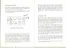
cable are necessary which can easily be made from 240 ohms ribbon cable.
A ribbon cable with a length of 3.70 m has to be short-circuited at both
sides. Then one of the cores has to be cut up exactly in the middle and
both ends have to be connected to the two cores of an additional cable
(see illustration page 8). This results in a loop dipole aerial with 240 ohms
impedance. The 3.70 m part of the cable is the actual aerial which has to be
installed vertically. The conducting cable connected in the middle may be
as long as it is necessary for the installation of the equipment. This symme-
trical conducting cable has to be connected to the receiver, the aerial input
of which is unbalanced, through the balancing devise TS 201 which is avail-
able as accessory part.
In case of receivers with spezial frequencies being used the length of the
dipole aerial can be calculated by means of the following formula:
125
length (m) = frequency (megacps)
The diversity cable TV 201 with a length of 10 m can be supplied additio-
nally for diversity operation with receivers not being located side by side.
The telescopic aerial TA 203 preferably can be used if there is lack of time
for installation of aerials. It can be fixed at the lower socket for the aerial
(1) at the receiver.
Replacement of tubes in the receiver T 201
All tubes of same make and type may be replaced without regarding any
hints.
.
Please, don't forget to regard the legal regulations issued by the competent
authority in your country before setting up the Mikroport. On the territory
of the Bundesrepublik Deutschland the form of application contained in
this instruction manual has to be filled in and sent to th~ competent
Oberpostdirektion.
19
I