


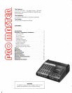
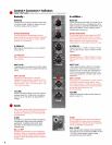
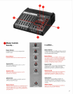
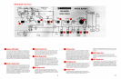
Controls Connectors Indicators
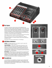
Peak Indicatorsg
Equalizer-
FEEDBACK FINDERTM
-
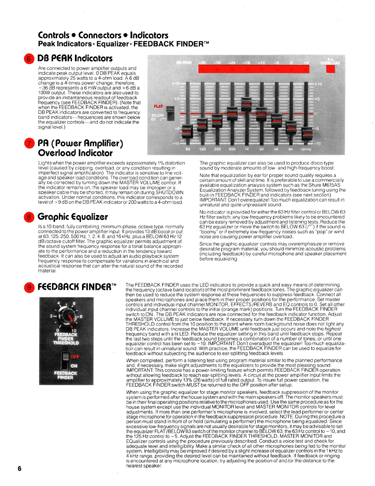
DB PCAH Indicators
Are connected to power amplifier outputs and
Indicate peak output level. 0 DB PEAK equals
approxlmately 25 watts to a 4-ohm load. A 6 dB
change
is a 4-tlmes power change; therefore.
-36 dB represents a 6
mW output and +6 dB a
100W output. These Indicators are also used to
provide an instantaneous readout of feedback
frequency (see FEEDBACK FINDER). (Note that
when the FEEDBACK FINDER is activated, the
DB PEAK
indicators
are converted to frequency
band
indlcators-frequencies are shown below
the
equal~zer controls-and do not indicate the
signal level
)
PA (Power Amplifier)
Overload Indicator
L~ghts when the power ampllfler exceeds approx~mately
1%
dlstortlon
level (caused by clipping overload or any
condition
result~ng ~n
Imperfect signal ampliflcatlon) The lndlcator 1s sensltlve to line volt-
age and speaker load
condltlons The overload condtioncan gener-
ally be corrected by
turnlng down the MASTER VOLUME control If
the
lndlcator remains on the speaker load may be Improper or a
speaker cable may be shorted
It may remaln on durlng SHUTDOWN
actlvatlon Under normal
conditions
th~s Indicator corresponds to a
level of
+9
dB on the DB PEAK ind~cator or
200
watts to a 4-ohm load
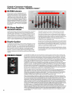
Graphic Cqualizer
Is a 10-band fully comb~nlng m~n~mum-phase octave type normally
connected to the power
ampl~fler Input It provldes 13 dB boost or cut
at 63 125 250 500 Hz 1
2
4
8
and 16 kHz plus a BELOW63 Hz 12
dB1octave cutoff fllter The graphic equallzer permits adjustment of
the sound system frequency response for a tonal balance
approprl-
ate to the performance and a reduction In the tendency toward
feedback It can also be used to adjust an audio playback system
frequency response to compensate for
variations
in electrical and
acoustical
response that can alter the natural sound of the recorded
materlal
The graphlc equallzer can also be used to produce disco-type
sound by moderate amounts of low- and high-frequency boost
Note that
equalizat~on by ear for proper sound qual~ty requires a
certaln amount of skill and tlme. It is preferable to use acommerc~ally
available
equalization analysls system such as the Shure M615AS
Equallzatlon Analyzer System, followed by feedback tunlng uslng the
bu~lt-in FEEDBACK FINDER and Indicators (see next section).
IMPORTANT Don't
overequallze! Too much
equalization
can result In
unnatural and qu~te unpleasant sound
No Indicator
1s provlded for eltherthe 63 Hzfllter control or BELOW 63
Hzfilter swltch, any low-frequency problems lhkely to be encountered
can be
eas~ly removed by adjustment and lhstenlng tests Reduce the
63 Hz equallzer or move the
swltch to BELOW 63
(r)
~f
the sound is
boomy' or
~f
extremely low-frequency noises such as 'pop' or wind
nolse are causlng power ampllf~er overload
Since the graphic equallzer controls may overemphasize or remove
desirable program
materlal you should minlmlze acoustic problems
(~ncluding feedback) by careful m~crophone and speaker placement
before
equallzlng
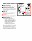
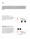
The FEEDBACK FINDER uses the LED lndlcators to provide a qulck and easy means of determlnlng
3
FCCDf3ACH FINDQRTM
the freauencv (octave bandocation, of the most ~rominent feedback tones The ara~hic eaualizer can
then be usedto reduce the system response at these frequencies to suppress feedback Connect all
speakers and microphones and place them
In thelr proper posltlons for the performance Set master
controls and
ind~vidual Input channel MONITOR. EFFECTSIREVERB and EQ controls to 0 Set all other
lndlvldual Input channel controls to the lnltlal (orange mark) posltlons Turn the FEEDBACK FINDER
swltch to ON The DB PEAK lndicators are now connected for the feedback ind~cator functlon Adjust
the MASTER VOLUME to just below feedback If necessary turn down the FEEDBACK FINDER
THRESHOLD control from the 10
pos~t~on to the point where room background noise does not lhght any
DB PEAK
lndlcators Increase the MASTER VOLUME unt~l feedback just occurs and note the h~ghest
frequency band with a lit LED Reduce the equalizer settlng in thls band untll feedback stops Repeat
the last two steps until the feedback sound becomes a
combination
of a number of tones or until one
equal~zer control has been set to -10 IMPORTANT Don t overadjust the equal~zerl Too much equaliza-
tlon can result In unnatural sound Wlth practlce the FEEDBACK FINDER can be used to equalrze for
feedback
w~thout
subjecting
the aud~ence to ear-spl~tting feedback levels
When completed perform a
lhstenlng test uslng program materlal s~mllar to the planned performance
and
if necessary make sl~ght adjustments to the equal~zers to prov~de the most pleasing sound
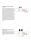
IMPORTANT This console has a
power-l~miting feature whlch permits FEEDBACK FINDER operatlon
wlthout allowlng feedback to reach ear-spl~tting levels A clrcult at the power ampllfler Input limlts the
amplifier
to approxlmately 13% (26 watts) of full rated output To Insure full power operatlon the
FEEDBACK FINDER
swltch
MUST
be returned to the OFF pos~t~on after setup
When using the graphic equallzer for stage
monltor speakers, feedback
suppression
of the monltor
system is performed after the house system and wlth the maln speakers off The monitor speakers must
be
In thelr f~nal
operating
positions
relatlve to the mlcrophones used Use the same procedure as for the
house system except use the
lndlvldual MONITOR level and MASTER MONITOR controls for level
adjustments If more than one performer's microphone
1s involved select the lead performer or center
stage mlcrophone
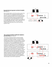
foroperat~on In thefeedbacksuppress~on procedure NOTE Dur~ng thls procedure a
person must stand
In front of or hold (slmulatlng a performer) the mlcrophone belng equalized Slnce
excessive low-frequency signals are not usually deslrable for stage mon~tors, ~t may be advisable to set
the
equal~zer FLATIBELOW 63 switch of the monltor channel to BELOW 63, the 63 Hz control to -10, and
the 125 Hz control to
-5
Adjust the FEEDBACK FINDER THRESHOLD MASTER MONITOR and
EQuallzer controls uslng the procedure
previously
descr~bed Conduct a volce test and check for
adequate level and
~ntelllglb~lity Make a s~m~lar check of all other mlcrophones belng fed to the mon~tor
system lntell~g~b~lity may be improved if deslred by a sl~ght increaseof equal~zercontrols in the 1 kHz to
4
kHz range provldlng the deslred level can be maintamed w~thout feedback If feedback or ringing
1s encountered at any mlcrophone location try
adjusting
the positlon of and/or the dlstance to the
nearest speaker