


12
Inhibiting Gating for Unwanted Sounds
As described in the Operating Principles section, MaxBus attempts to acti-
vate only one microphone per sound source. Muting a microphone channel
prevents its audio from appearing at the mixer's output. However, the mut-
ed microphone still communicates with other mic channels via MaxBus. A
sound source picked up by a muted microphone will not activate other mi-
crophones.
Sound sources that may cause unwanted microphone channel activation
include:
• A noisy fax machine or printer
• A squeaky door
• A paging system loudspeaker
• An audio teleconferencing return signal loudspeaker
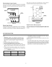
The SCM810 can prevent these and similar sounds from activating micro-
phones by taking the following steps.
1. Place one microphone near the unwanted sound source. Connect that
microphone's signal to a channel input,
-or-
connect the unwanted sound source directly into a Mic/Line channel
input.
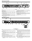
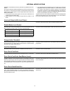
2. Mute that channel using the logic terminal (see Figure 16-Channel 1 is
muted).
3. Adjust that channel's gain control just to the level where other micro-
phones in the system do not activate for the unwanted sound. If the
channel gain is set too high, other system microphones will be difficult
to activate for desired sounds. If set too low, unwanted sounds will
continue to activate other microphones.
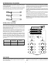
INHIBITING GATING UNWANTED SOUNDS
FIGURE 16
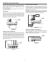
Loudspeaker Muting
Some applications require a loudspeaker to be placed near each talker to
provide audio reinforcement, or to permit telephone conversation or
conference monitoring. Each loudspeaker can cause feedback unless it is
automatically switched off when the talker near it speaks. To provide this
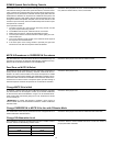
function, connect the GATE OUT terminal of each channel to a separate
loudspeaker muting relay as shown in Figure 17 (Channels 1, 3 and 5
shown modified). Recommended relays are Omron G6B-1174P-US-DC12,
Potter & Brumfield R10-E1Y2-V185, or equivalent (available through
Digi-Key and Newark Electronics).
NOTE: A diode across each relay coil is required to suppress inductive volt-
age spikes which may damage the SCM810.
An existing sound system using 24-volt relays can be used with the
SCM810 without modification if the relay coil current draw is under 500 mA.
LOUDSPEAKER MUTING
FIGURE 17
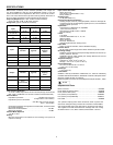
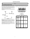
“Filibuster” Mode
In normal operation, when several people talk, each microphone gates on
so that no speech is missed. In “filibuster” action, a microphone that is gat-
ed on prevents other microphones from gating on. Once a microphone has
gated on, other microphones cannot gate on until the talker has paused
long enough for that microphone to gate off. Thus the person talking has
the floor and cannot be interrupted.
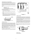
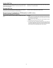
To establish this function, first perform the internal Mute to “Inhibit” modifi-
cation (see Internal Modifications). Then connect all the MUTE IN pins of
the modified channels together, all the GATE OUT pins of the modified
channels together, and the GATE OUT pin of one modified channel to the
MUTE IN pin of another modified channel (see Figure 18-Channels 1, 2
and 3 modified). Turn the Last Mic Lock-On switch (SW702, position 2) to
off.
NOTE: To prevent high-frequency oscillation, do not wire a channel's GATE
OUT pin to its own MUTE IN pin unless the Mute to “Inhibit” change has
been made.
“FILIBUSTER” MODE
FIGURE 18
Inhibit Function
See Internal Modifications.
M1
LOGIC
GROUND
+
–
12 V
POWER
SUPPLY
G5G3
G1
LOGIC
GROUND
D = 1N4148
FROM
POWER
AMP
JUMPER
G1 M1
G3
M3
M2G2
LOGIC
GROUND