


8
NETWORKING MULTIPLE MIXERS
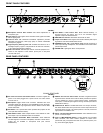
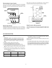
If additional inputs are needed, more SCM810 mixers (as many as 50) can
be “linked” using supplied link cables. Such a configuration can provide up
to 400 microphone inputs.
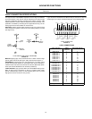
To link multiple mixers, connect the LINK OUT of the first mixer to the LINK
IN of the next mixer, and so on (see Figure 8). Leave the LINK IN jack of
the first mixer and the LINK OUT jack of the last mixer unconnected.
LINKING MIXERS
FIGURE 8
As long as the link jacks of all mixers are connected (out-to-in, sequentially,
leaving one Link In and one Link Out jack unconnected), the automatic mix-
ing functions will be shared by all units. All input signals appear at all linked
mixer outputs. There is no master/slave relationship.
The output controls and functions of each linked mixer are post-link and do
not affect the signals appearing at other linked mixer outputs. Each mixer's
Master level control only controls its own output. Each output can be used
independently.
NOTE: The actual off-attenuation in the 15 dB switch position increases as
more mixers are linked. This reduces excessive noise and reverberation
contributed by the increased number of attenuated microphones.
In a linked system, the Aux input of any mixer appears at each linked mix-
er's output. See Internal Modifications to defeat the linking of Aux signals.
IMPORTANT: When using the logic terminals on linked mixers, connect the
LOGIC GROUND terminals of each unit together. Switching clicks may re-
sult if this is not done.
GLOBAL/LOCAL FUNCTIONS
The Global/Local switch selects which input channels appear at that linked
mixer's output. Set to the Global position, all input channels appear at that
mixer's output. Set to the Local position, only its own eight input channels
appear at that mixer's output. The Master level control, in any mode, only
controls the level of its own output.
The Master level control is independent of the Global/Local switch. The out-
put level of each mixer is affected only by its own Master control. All auto-
matic functions (such as Last Mic Lock-on and MaxBus) are connected on
all linked mixers and are not affected by the Global/Local switch.
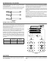
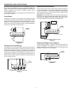
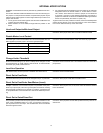
An example of the possibilities of this setup is shown in Figure 9 Here two
SCM810s are set to Local, and the resulting sound distribution provides
local sound reinforcement while avoiding feedback. This is a simple
“mix-minus” setup. The third SCM810 is set to Global and feeds a tape
recorder, At the same time, the automatic functions (Last Mic Lock-On,
etc.) remain common to all mixers. The following table summarizes the
mixer settings.
LINKED SCM810 MIXERS
FIGURE 9
LINK CABLES
Additional link cables are available as Shure Part No. 95A1143 (305 mm-
12 in.). Longer cables in a variety of lengths are available from Apple Com-
puter as computer printer
connections; they are variously referred to by Apple as “shielded serial
cable with two mini DIN-8 connectors,” and “Apple System Peripheral-8
Cable.”
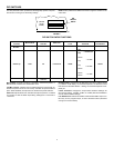
MIXER Link Global/
Local Switch
Audio Output
Contains...
A Local A
B Local B
C Global A, B, C
LOUDSPEAKER LOUDSPEAKER
SCM810 “A” (LOCAL)
SCM810 “B” (LOCAL)
LINK
SCM810 “C” (GLOBAL)
RECORDER