


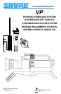


– 4 – EnglishEnglish
READ ME FIRST!
A quick guide to operating your Shure VP Wireless Microphone System
BATTERY INSTALLATION
1. Open the battery compartment on the VP3 Receiver and, while observing proper
battery polarity (“+/–”), insert a fresh 9–volt alkaline battery.
2. Open the battery compartment on the body–pack or hand–held transmitter. While
observing proper battery polarity (“+/–”), insert a fresh 9V alkaline battery.
NOTE: If a 12 Vdc power source is to be used, plug a dc adapter cable (not sup-
plied) into the DC power input on the side of the receiver. If dc power is used, it is
not necessary to install a battery in the VP3 Receiver.
MOUNTING THE VP3 RECEIVER TO THE CAMERA
1. To mount the VP3 Receiver to a video/film camera using hook-and-loop (VELCRO
type) fastener strips, attach one strip to the VP3 Receiver and the matching strip to
the camera. Then mate the strip on the VP3 Receiver to the strip on the video/film
camera.
2. To mount the VP3 Receiver on a video/film camera with a “shoe” attachment, re-
move the belt clip from the receiver and replace it with the supplied “shoe” adapter,
using the same screw. Then slide the VP3 Receiver into the shoe mount on the
camera.
NOTE: The VP3 Receiver can be mounted on a camera horizontally or vertically.
In either case, the antenna must be positioned vertically.
CABLE CONNECTIONS
1. Connect the VP3 Receiver audio output to the camera or mixer microphone input,
using the supplied WA460 audio cable. Make certain the wireless receiver audio
signal is compatible with your camcorder’s input circuitry. Make certain the cable
hangs freely between the receiver and the audio input.
NOTE: If the microphone input requires an XLR-type connector, use the Shure
WA450 cable (available as an accessory). Some camera inputs may require a
stereo–to–mono adapter (not supplied); refer to the Cable Connections section.
2. To monitor received audio, plug the headphones cable (not supplied) into the VP3 Re-
ceiver PHONES connector.
3. On a body–pack transmitter, connect the microphone cable to the 4–pin connector
on the transmitter.
OPERATION
1. Slide the VP3 Receiver POWER switch into the ON position. The POWER/RF light
on the receiver will illuminate green, indicating a good battery.
2. Set transmitter POWER and MIC switches to the ON position. The green POWER
light on the transmitter will illuminate, indicating a good battery.
3. Verify that the POWER/RF light on the VP3 Receiver changes from green to
orange and is steadily illuminated. This indicates that the transmitter signal is be-
ing received.
4. Talk, sing, or play a musical instrument into the microphone. The red AUDIO PEAK
indicator on the VP3 Receiver should flicker occasionally. If the red AUDIO PEAK
indicator on the VP3 Receiver is always on or is never on, refer to the Audio Gain
Adjustments section in the user’s manual. If optional monitor headphones are
used, adjust the headphones LEVEL control until the audio signal is heard clearly.