


10
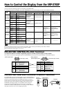
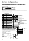
How to Control the SRP-X700P from External Equipment
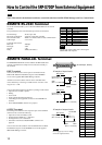
REMOTE RS-232C Terminal
Use of this terminal enables you to control the SRP-X700P from an external
controller.
The specifications of the communication protocol are shown below.
Terminal shape : D-sub 9-pin, male
Electrical specifications : Conforms to RS-232C standard
Recommended cable : Multi-core shielded cable for data communication
Cable length : 15 m or less
Communication format
Baud rate : 9600 bps
Bit length : 8 bits
Stop bit : 1 bit
Parity : ODD (odd number)
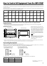
REMOTE PARALLEL Terminal
The REMOTE PARALLEL terminal enables the SRP-X700P to be
remotely controlled with a simple circuit connected externally to
this terminal.
INPUT terminal
You can set the functions of the respective terminals from the
PARALLEL INPUT FUNCTION setup box in the REMOTE
screen of the supplied SRP-X700P Manager software.
All faders and sound volume controls can be controlled from a
remote location by connecting a variable resistor as shown, in the
range of 0 to
–
∞ dB.
You can perform the following operations by adding a make contact.
• Input selection of LINE 4 system
• Muting
• Scene recall
• Sound volume adjustment (Up/Down)
• Controlling the AV equipment connected to the CONTROL S
terminal
• Power-ON/STANDBY selection of a projector
OUTPUT terminal
The turning ON conditions of the respective pins of the OUTPUT
terminal can be set from the following.
• Input selector state of LINE 4 system
• Turning ON the OVER and
–
∞ indicators
• Turning ON the scene recall button
• Generation of the Power-ON/STANDBY command of a
projector
You can select the ON conditions from the PARALLEL OUTPUT
FUNCTION setup box on the REMOTE screen of the supplied
SRP-X700P Manager software.
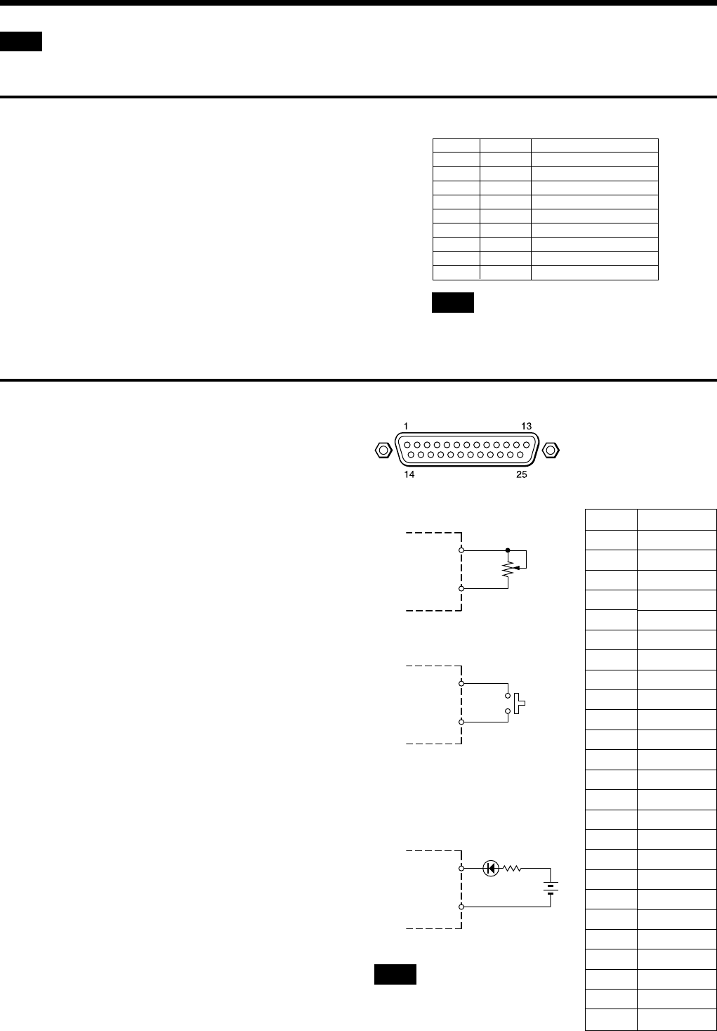
(D-sub 25-pin, female)
<Example of input circuit>
10 kΩ
Curve-B variable
resistor
GND
(Nos. 1, 14 and 25)
<Example of output circuit>
GND
(Nos. 1, 14 and 25)
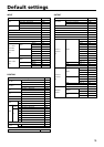
Pin No.
1
2
3
4
5
6
7
8
9
10
11
12
13
14
15
16
17
18
19
20
21
22
23
24
25
Function
GND
INPUT1
INPUT2
INPUT3
INPUT4
INPUT5
INPUT6
INPUT7
INPUT8
INPUT9
INPUT10
INPUT11
INPUT12
GND
OUTPUT1
OUTPUT2
OUTPUT3
OUTPUT4
OUTPUT5
OUTPUT6
OUTPUT7
OUTPUT8
OUTPUT9
OUTPUT10
GND
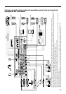
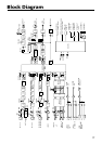
SRP-X700P
SRP-X700P
40 mA MAX
N
SRP-X700P
24 V
MAX
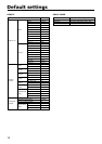
Pin No. Signal Function
1 FG Frame ground
2 RD Receive data
3 TD Send data
4 ER Data terminal ready
5 SG Signal line ground
6 DR Data set ready
7 RS Request to send
8 CS Clear to send
9 N. C Not connected
0 dB
–
∞ dB
Note
Do not apply any reverse voltage
across the output terminal.
Note
Use the null modem cable when connecting the
SRP-X700P with computer.
Note
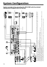
The USB terminal is the dedicated terminal to control this unit from the SRP-X700P Manager and User Control Panel.
Input terminal
(No. 2 to No. 13)
Output terminal
(No. 15 to No. 24)
Input terminal
(No. 2 to No. 13)
GND
(Nos.
1,
14 and 25)