14
System Configuration
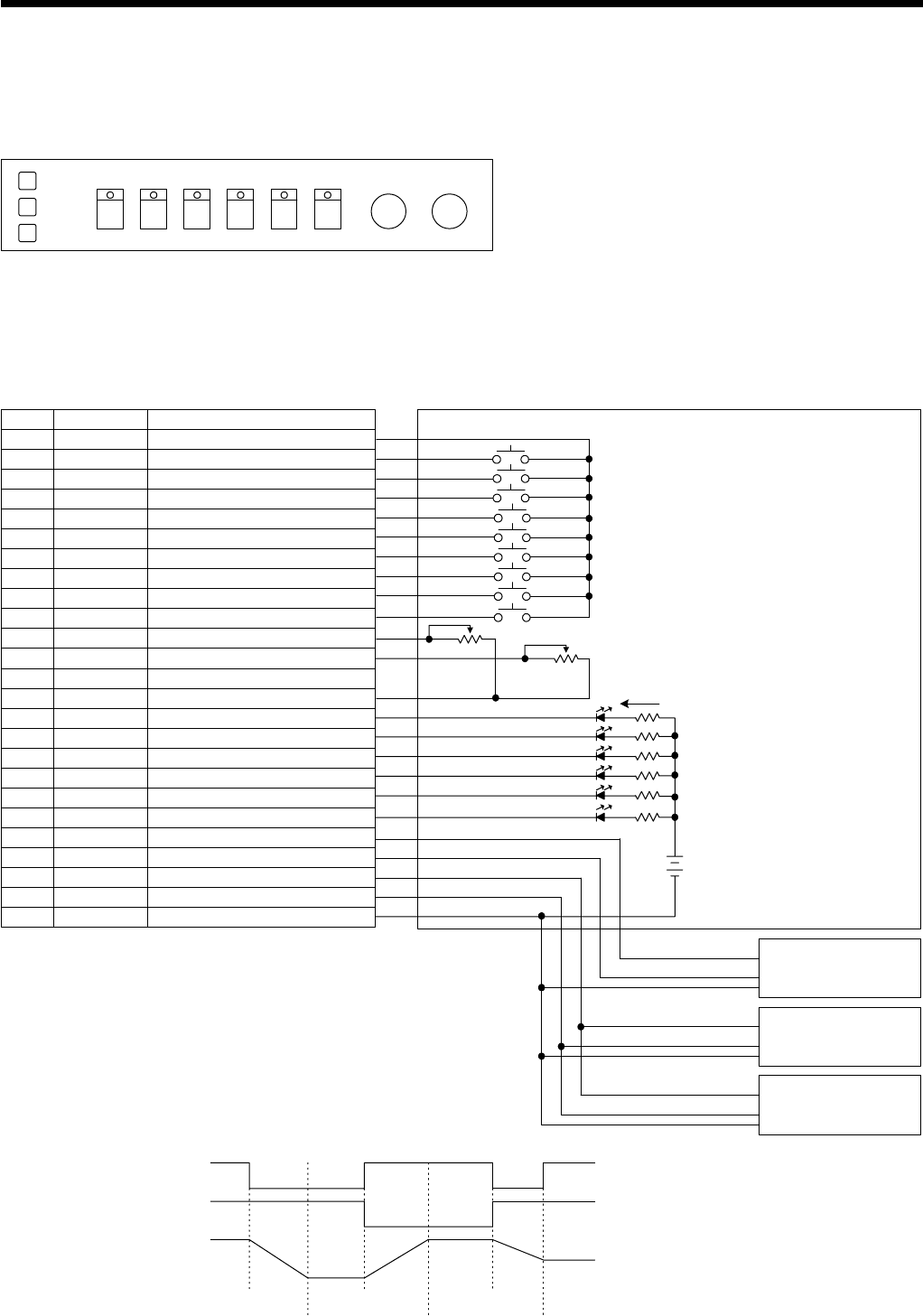
System example when operating the SRP-X700P from the REMOTE
PARALLEL terminal
The REMOTE PARALLEL terminal of the SRP-X700P is shipped from the factory with the default setting on the premise of the external
operation panel as described below.
START button (SCENE No. 1 recall): Sets OUTPUT7 and OUTPUT9 to ON to lower the screen, to close the curtain, to darken the illumination and to start presentation.
FINISH button (SCENE No. 2 recall): Sets OUTPUT8 and OUTPUT10 to ON to raise the screen, to open the curtain, to turn on the illumination and to end the presentation.
EMG STOP button (SCENE No. 3 recall): Sets OUTPUT7 through OUTPUT10 to OFF to stop moving the screen and the curtain, and to turn on the illumination.
Selector block: Switches the LINE4 INPUT terminals A through F.
MIC volume control: Controls the microphone sound volume.
AV volume control: Controls sound volume of the AV equipment.
VHS DV
Camera
Stand
DVD PC1 PC2 MIC AV
START
FINISH
EMG STOP
1
2
3
4
5
6
7
8
9
10
11
12
13
14
15
16
17
18
19
20
21
22
23
24
25
GND
GND
VHS selection
DV selection
Camera selection
DVD selection
PC1 selection
PC2 selection
START
FINISH
EMG STOP
Microphone sound volume
AV equipment sound volume
———
GND
VHS selection tally
DV selection tally
Camera selection tally
DVD selection tally
PC1 selection tally
PC2 selection tally
Lowers the screen.
Raises the screen.
Close the curtain/turn off illumination.
Open the curtain/turn on illumination.
GND
VHS VCR selector button
DV VCR selector button
Picture presentation camera selector button
DVD selector button
PC1 selector button
PC2 selector button
START (presentation start) button
FINISH (presentation finish) button
Emergency stop button
Microphone sound volume control (10kΩ B-curve)
AV equipment sound volume control (10kΩ B-curve)
VHS VCR selection LED
DV VCR selection LED
Picture presentation camera selection LED
DVD selection LED
PC1 selection LED
PC2 selection LED
SRP-X700P REMOTE PARALLEL terminal
D-sub 25-pin connector
Pin No.
Terminal name
Function name
External operation panel
INPUT1
INPUT2
INPUT3
INPUT4
INPUT5
INPUT6
INPUT7
INPUT8
INPUT9
INPUT10
INPUT11
INPUT12
GND
OUTPUT1
OUTPUT2
OUTPUT3
OUTPUT4
OUTPUT5
OUTPUT6
OUTPUT7
OUTPUT8
OUTPUT9
OUTPUT10
GND
LED
40mA or less
DC 24V or less
Lowers the screen.
Screen
interface box
Curtain
interface box
Illumination
interface box
Raises the screen.
Closes the curtain.
Opens the curtain.
Turns off illumination.
Turns on illumination.
Precaution on the environment interface box specifications
• The REMOTE PARALLEL output terminal provides the open-collector output of
alternate operation. It means that the output terminal keeps outputting the ON signal
after an output command is issued to move the environment equipment for scene recall
and others, regardless of the operating condition of the environment equipment. The
environment equipment motors should be stopped when you want to stop raising or
lowering the screen or curtain, by the Interface Box.
• The Emergency Stop signal turns off the output signals at the OUTPUT7 to
OUTPUT10 terminals.
Please create an Interface Box that stops moving the screen and the curtain, and turns
on illumination when the output terminals are turned off.
OUTPUT7,9
Raise, open and light-on
Stop and light-on
Lower, close and light-off
OUTPUT8,10
Operation of
environment
equipment
ON
OFF
OFF
ON
START
(SCENE No. 1 recall) (SCENE No. 2 recall) (SCENE No. 1 recall)
(SCENE No. 3 recall)
END END
FINISH
EMG STOP
START


