


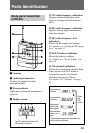

Parts Identification
36
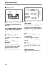
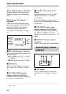
B AF (audio frequency) indication
Appears whenever the output audio
signal is stronger than the reference
level.
C GP (group)/CH (channel)
indication
Shows the reception channel group
and channel number. Each time you
press the SET button, the channel
indication changes as follows.
For details, see “Settings” on page
47.
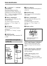
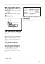
7 RF (radio frequency) indicator
The color indicates the strength of the
RF input signal.
On in green: RF input is 25 dBµ*
or more.
Off: RF input is less than 25 dBµ*.
8 SET button
Press to change display parameters.
For details, see “Settings” on page
47.
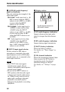
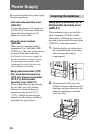
9 TUNER OUTPUT (audio
output) connector (XLR type)
Connect to the audio input connector
of a mixer or amplifier, etc.
0 LEVEL (audio output level)
switch
Sets the output level of the TUNER
OUTPUT connector to –28 dBm
or –58 dBm.
Select the setting according to the
input level of the equipment connected
to the tuner.
qa TRS PHONE (tuner audio
output) connector (1/4-inch jack)
Connect to the audio input connector
of a mixer or amplifier, etc. The
output level from this connector is –30
dBm.
qs DC IN 9V (DC power input)
connector
Connect the supplied AC adapter here.
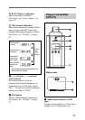
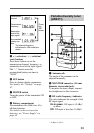
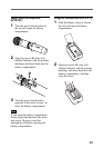
Diversity tuner module
(URX-M1)
1 SET button
Press to change display parameters.
For details, see “Settings” on page
47.
......................................................................................................................................................................
* 0 dBµ = 1 µVEMF
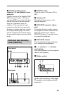
Reception
channel
group and
number
Reception
frequency
Press
the
SET
button.