


effect individually. The middle position of this control will
have the value of the individual selected effect preset indi-
cated in the diagram above.
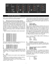
18 DEPTH
With this control you can adjust the intensity of the LFO
19 SELECT
With this switch you can choose the channel on which the
effect should work. The following 6 positions are available:
MIC Microphone channel
CH1 PGM1
CH2 PGM2
CH3 PGM3
CH4 PGM4
MA Master section
20 ON / OFF / FLASH
With this switch you can turn the effect on or off. In the
FLASH position you can temporarily trigger the effect.
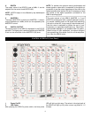
INPUT CHANNELS 1-4
Input channels 1-4 are identical. Therefore we will only
describe PGM1:
21 SELECT
With this switch you can select one of the three inputs:
TT PHONO (M)
L1 LINE 1 (I)
L2 LINE 2 (H)
22 CROSSFADER
This switch will select to which side of the crossfader the
the signal of the selected channel should be routed. The
blue LED’s to the left and right of the crossfader will indi-
cate the chosen selection:
A The signal comes through the left side of the cross
fader
POST The signal bypasses the crossfader
B The signal comes through the right side of the
crossfader
23 GAIN
24 LED Clip
With this control you can set the volume of the incoming
signal of your selected input (SELECT 21). When setting
this control in the right position, the CLIP-LED will only light
up occasionally during really loud peaks of audio signals.
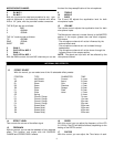
25 AUX
With this control you can set the volume and intensity of the
auxiliary output.
26 TREBLE
27 BASS
28 MIDDLE
29 MID FREQ
With the EQ you can set the level of each frequency.
Furthermore the EQ can be used to isolate certain frequen-
cies. This is very easy and effective with the high quality
and very strong filter-type parametric EQ on your VRM10.
NOTE : As the VRM-10’s EQ is so powerful, you may have
to carefully adjust the GAIN (23) while using the EQ (26-29)
30 CHANNEL FADER
With the fader you can set the volume of the input channel
31 PFL
In the headphones you will hear the signal of the master
output if none of these buttons are activated: PFL (31),
EFFECT (57) and FILTER (56). If you press any PFL switch
you will here the selected audio signal before the master
output signal.
NOTE : It is possible to select more than one channel with
the PFL option.
CROSSFADER
32 Crossfader
With the crossfader you can control and mix the various
audio channels. You must have selected which channel
runs through the crossfader, though. This selection can be
made with the CROSSFADE switch (22).
33/34 TRIGGER
With both these buttons you can punch-in the audio signal
on whichever side of the crossfader you would like to hear
it, no matter in which position the crossfader is. By press-
ing both buttons you will hear both audio signals on either
side of the crossfader.
4
The VRM10 is equipped with high quality faders.
Nevertheless a fader has no life-time warranty (see war-
ranty section) as it is used in a heavy duty way. If the
fader ever needs replaced, we have made it easy to be
replaced:Just loosen the 4 screws around the fader;
then disconnect the fader and replace with the new part.
Connect the fader back into the socket and screw the 4
screws back into their holes.
Using modern VCA-technology in the VRM10 prevents
early damage of the crossfader. Nevertheless, once in a
while every fader gets worn out and needs to be
replaced. To change the crossfader easily you only need
to unscrew the two screws on the fader and disconnect
the socket. Then you need to connect the new fader and
put the screws back into their place.