


35/36 CROSSFADE LED’s
The LED’s located left and right of the crossfader indicate,
which input channel lies on which side of the crossfader
according to the crossfader assign switch (22).
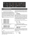
37 CROSSFADE CURVE
With this control you adjust the crossfade curve. When the
knob is set completely to the left, the crossfader curve is
set to a sharp on/off cut on both sides. If the knob is set
completely to the right, the crossfader will fade smoothly
from side to side.
DJ FILTER
The DJ Filter consists of two 24dB/Octave analog filters,
which can be combined by setting the FILTER SELECT
switch (38).
38 FILTER SELECT
These positions are available:
BAND The filter works as bandpass
OFF The filter is switched off
NOTCH The filter works as a notch filter
39 CUT OFF HIGH
In the BAND position, this is used as a lowpass frequency
control. In the NOTCH position, it works as a highpass
frequency control.
40 RESONANCE HIGH
This creates a gradual increase of up to 6dB of resonance
of the CUTOFF frequency is as it turned to the right.
41 CUT OFF LOW
In the BAND position, this will act as highpass frequency
control. In the NOTCH position, it will act as lowpass
frequency control.
42 RESONANCE LOW
This creates a gradual increase of up to 6dB of resonance
of the CUTOFF frequency is as it turned to the right.
43 FLASH
The Flash function temporarily disables the filter while the
button is pressed.
NOTE : In BAND mode it may be possible to eliminate the
output signal totally if the controls are used heavily. The fre-
quency controls (39 and 41) act as high torque kill switch-
es.
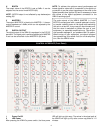
MASTER SECTION
44 TUBE
This switch turns the tube-preamplifier on or off.
45 TUBE INDICATOR (MAGIC EYES)
Both indicator tubes for the left and the right channel will
indicate the output volume of the mixer, except the
MIC channels. When the tube lines meet in the middle you
have the ideal output peak. Additionally, the maximum peak
will be indicated by the master clip LED’s (46).
46 SIGNAL/ CLIP LED’s
The green LED’s will indicate a well balanced output signal.
To achieve the optimum peak level at maximum perform-
ance, the green LED’s should always light up, as soon as
any signal runs through your VRM10. The red LED’s will
indicate if the peak is too high. These red LED’s should only
peak occasionally within high volume passages from the
audio source fed through the mixer. If this is not possible
you may need to adjust the volume within the individual
channel faders.
47 SEND
With this you control the SEND volume of the external
effect path (max level is set at 0dBu).
48 RETURN
With this you control the volume of the external effect sig-
nal returned to the mixer.
NOTE : When the internal effect (19) is turned on and set to
MASTER (20), the external effect will be automatically
switched off.
49 BOOTH
With this you control the volume of the BOOTH output (max
level is set at 0dBu).
50 BALANCE
With this knob you can control the balance (pan) for the
MASTER outputs.
51 MASTER 1
With this knob you can control the MASTER 1 output vol-
ume [max level is set at 0dBu, or +6dBu according to the
attenuation switch located on the back panel (R)]
52 MASTER 2
With this knob you can control the MASTER 2 output vol-
ume (max level is set at +6dBu)
MONITOR
53 MONITOR
With this knob you can control the volume of the
headphones
54 HEADPHONE JACK 3,5mm / 1/8”
55 HEADPHONE JACK 6,3mm / 1/4”
Both jacks are switched parallel. You can connect two pairs
of phones at the same time with an impedance of 30-400
5