


Model 233 User Guide Issue 1, September 2007
Studio Technologies, Inc. Page 17
Pushbutton Labeling
The three pushbutton switches used in
the Model 233 were selected for several
reasons. Foremost was the fact that they
are highly reliable, using gold-plated con-
tacts for long life in less-than-ideal environ-
ments. A second reason was that applying
customized labels to the button caps
would be very simple. The labels, text
printed on clear material, are placed under
the clear caps on the top of the buttons.
From the factory the left button is labeled
COUGH, the center button is labeled
TALKBACK 1, and the right button is
labeled TALKBACK 2. This was selected
to be appropriate for many on-air applica-
tions in English-speaking locations. But
it’s expected that these may need to be
changed to meet the needs of specific
applications.
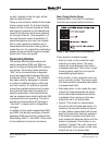
As a “head start” for some applications,
a clear sheet with a number of commonly
used button designations printed on it is
included in the shipping carton. These
were created at the factory using a stan-
dard personal computer graphics program
and laser printed onto 3M CG3300 trans-
parency film. The desired button labels
can be cut out with a pair of scissors, fol-
lowing the printed guide lines that indicate
the required size.
The clear lens on top of each button cap
can be removed with a fingernail or small
screwdriver. Be certain not to scratch the
button if a screwdriver or other small tool
is used. The clear label can be removed
and replaced. The button cap is then
snapped back into the top of the button
housing using finger-pressure only. No
tool is required to replace the button cap.
If you need to make your own labels the
process is quite simple. Use a personal
computer to create the desired text. The
finished label size should be 0.625-inches
(15.8 mm) square. The completed artwork
can then be printed on transparency film
sheets using a laser or inkjet printer. These
sheets are readily available from most
office supply stores. A pair of scissors or
an X-ACTO® knife will complete the task.
Configuration
For the Model 233 to support the needs
of specific applications a number of
operating parameters must be configured.
These include microphone preamplifier
gain, phantom power on/off, headphone
source and output mode selection, and
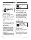
operating modes. One 12-position and
three 8-position DIP-type switch assemblies
are used to establish the desired configura-
tion. These switch assemblies are referred
to as SW1 through SW4, with individual
switches designated as SW1-1, SW1-2,
etc. The switch assemblies are accessed
through openings in the bottom of the
Model 233’s enclosure. The enclosure
does not have to be disassembled to
gain access to the switches.
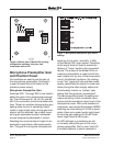
To prevent unauthorized personnel from
changing the configuration settings, a se-
curity plate is attached to the bottom of the
Model 233’s enclosure. For convenience,
attached to the security plate is a configura-
tion settings label. It provides a summary
of the configurable parameters and related
information. Refer to Appendix A for a
representative view of the label. The secu-
rity plate is held in place by means of four
rubber bumpers (“feet”) that have built-in
screws. Using your fingers, remove the four
bumpers so that the plate can be removed.
Refer to Figure 3 for a detailed view of the
configuration switch assemblies.