


Issue 1, September 2007 Model 233 User Guide
Page 18 Studio Technologies, Inc.
signal up to line level, nominally –2 dBu,
on the Model 233’s main output. Operating
at this signal level will help to ensure the
delivery of “clean” audio to the connected
device. The output of the Model 233’s mi-
crophone preamplifier is used by both the
main output and, by way of the compressor
circuit, the talkback functions. So creating
a nice “hot” signal will help maintain audio
quality, specifically the signal-to-noise ratio,
when driving the often-lengthy cable runs.
Unfortunately, there’s no “perfect” gain
setting that this guide can recommend.
The two issues that impact the setting are
output sensitivity of the connected micro-
phone and the acoustical output level of the
microphone’s user. With some headset mi-
crophones, such as the Sennheiser HMD25,
selecting an initial setting of 40 dB is appro-
priate. Users who speak loudly might need
to have the gain reduced to 30 dB. Quiet
users might need 50 dB of gain.
An LED indicator is provided as an aid
in correctly setting the gain of the micro-
phone preamplifier. Red in color, this LED
is located adjacent to switch assembly 1.
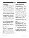
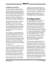
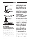
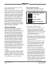
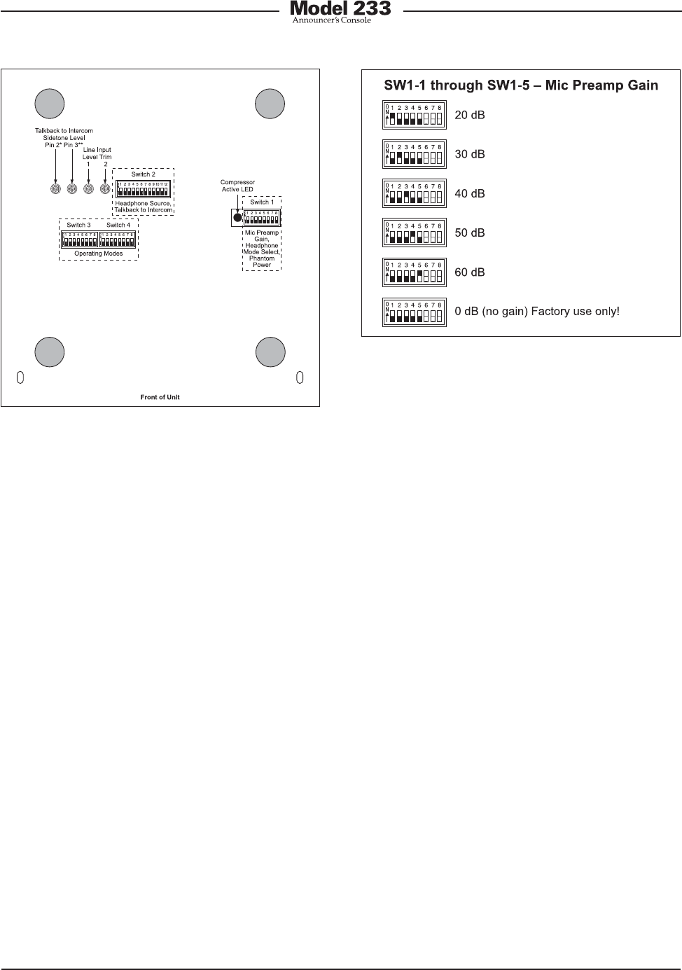
Figure 4. Microphone preamplifier gain switch
settings
Microphone Preamplifier Gain
and Phantom Power
Five switches are used to set the gain of
the microphone preamplifier. One switch
is used to select the on/off status of the
phantom power supply.
Microphone Preamplifier Gain
Switches SW1-1 through SW1-5 are used to
select the gain of the microphone preampli-
fier. The choices are 20, 30, 40, 50, and 60
dB. Only one switch should be enabled at a
time. There’s no problem changing the gain
setting while the unit is operating. Audio
clicks or pops might occur during gain tran-
sitions, but this shouldn’t be a major issue
as long as associated monitor loudspeak-
ers are temporarily attenuated or muted.
Selecting the correct amount of gain for an
application might take a little experimenta-
tion. The goal is to bring the microphone’s
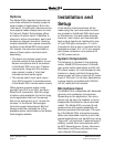
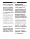
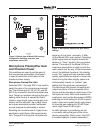
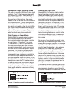
Figure 3. Bottom view of Model 233 showing
configuration switches, trim pots, and
compressor active LED