


Issue 1, September 2007 Model 233 User Guide
Page 20 Studio Technologies, Inc.
The line inputs are interfaced using two
connectors also located on the back pan-
el. Associated with line inputs 1 and 2 are
level trim potentiometers. They are pro-
vided so that audio sources with a wide
range of nominal levels can be effectively
used as cue sources. Please refer to the
Advanced Operation section of this user
guide for details on using the trim pots.
Audio associated with intercom channels
1 and 2 is provided by way of the intercom
interface whose connector is also located
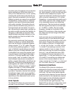
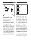
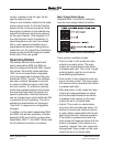
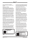
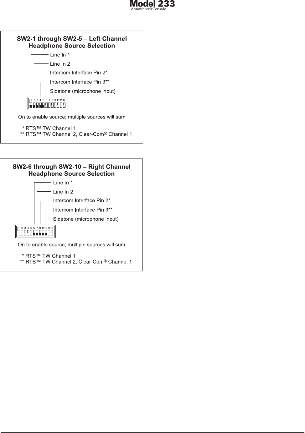
Figure 6. Left and right channel headphone
source selection settings
on the back panel. Two trim pots are
associated with the intercom channels.
They allow adjustment of the intercom
sidetone (null) level. This impacts the
amount of talkback audio signal that is
returned to a headphone output when a
talkback-to-intercom function is active.
The sidetone audio source comes from
the output of the compressor circuit as-
sociated with the microphone preamplifier.
This allows an announcer or other Model
233 user to receive a confirmation signal
of what is coming out of the main, and if
configured, talkback outputs.
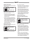
As previously discussed, each of the avail-
able input sources can be assigned to
the headphone output’s left channel, right
channel, or both the left and right chan-
nels. The Model 233’s circuitry allows any
combination of input assignments to be
made. For example, consider the situation
where a single-channel intercom line, with
audio present only on pin 3, is connected.
In this case it may be desirable to assign
this intercom audio source to both the left
and right channels. This would entail set-
ting switches SW2-4 and SW2-9 to their
on positions. All other switches would
remain in their off positions.
A more complex application might have
a broadcast-type 2-channel IFB circuit
connected to the intercom input and a
line-level audio signal from a golf event
“spotter” connected to line input 1. In
a case such as this, it would be typical
for IFB channel 1 to be assigned to the
headphone’s left channel, IFB channel
2 assigned to the right channel, and line
input 1 also assigned to the right channel.
This would allow both IFB channel 2 and
“spotter” audio to be heard in the head-
phone’s right-channel output. To achieve
this would require that switches SW2-3,