


Issue 1, September 2007 Model 233 User Guide
Page 40 Studio Technologies, Inc.
are specifically included so that a Model
233 can be customized to meet the many
specific needs that arise in broadcast and
related audio applications. Expected uses
for these locations include adding a 6- or
7-pin XLR-type connector to allow direct
connection of a broadcast headset. Other
uses include creating “loop through” or
“mult” functions for the line-level talkback
output or intercom interface connections.
The spare connector locations are com-
patible with the Neutrik DL-series of
connectors. For flexibility, versions are
available that provide from three to seven
contacts. For example, a compatible 3-pin
female connector would be Neutrik part
number NC3FD-L-1. To support headsets
the NC6FDS-L-1 is often used. This is a
6-pin female connector with the unique
Switchcraft 6-pin arrangement. The hard-
ware that secures the blank plates to the
Model 233’s back panel is also intended
to secure the replacement connectors.
If connectors are added to the Model
233’s spare connector locations adding
labels to those connectors can be helpful.
For a great look it is recommended that
Brother® P-Touch ¼-inch (6 mm) labels
be created. Tape material that prints white
text on a black background works out
well for the Model 233. The Brother label
cassette number TX-3151, white on black,
is appropriate for use with many of their
printers.
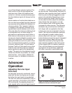
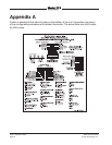
In addition to the spare connector loca-
tions on the back panel, provision has
been made to allow easy interconnection
with the Model 233’s printed-circuit-board-
mounted input and output connectors.
This was accomplished by including
numerous 3-position male “header” con-
nectors on the Model 233’s circuit board.
These headers, on 0.1-inch centers, are
wired in parallel with the Model 233’s con-
nectors. This “no solder” solution makes
customizing a Model 233 a simple pro-
cess. The headers, located on the Model
233’s printed circuit board, are Molex®
part number 22-23-2031. They mate with
Molex housing number 22-01-3037. To
make the interconnection, separate crimp
terminals are attached to loose wires and
then “snapped” into the housing. Molex
part number 08-50-0114 specifies crimp
terminals that are appropriate for wires of
22 to 30 gauge. These parts are available
worldwide from sources such as Digi-Key,
website www.digikey.com.
To make the process of connecting to the
Model 233’s headers a simple task an
interface cable kit, part number 31087, is
available from Studio Technologies. Each
kit includes five cable assemblies and a
length of heat-shrinkable tubing. Each
cable assembly consists of a mating con-
nector with three color-coded wires at-
tached. These wires, nominally 12 inches
in length, allow convenient soldering to a
connector slated to be installed in a spare
location on the Model 233’s back panel.
For reference, the wire color for pin 1 is
gray, pin 2 is yellow, and pin 3 is blue.
The heat-shrinkable tubing is provided
so that the connector solder cups can be
insulated from each other. It will also pro-
vide some strain relief to the solder joints.
Be certain to slip the desired length of tub-
ing over the wire prior to soldering a con-
nection! (If this writer had a dollar for every
time he forgot to put tubing on a wire (or
slip on a connector shell) before making
a solder connection…)
The Model 233’s enclosure must be
disassembled prior to installing connec-
tors in the spare locations. Four hex-head
machine screws, two on the bottom front