


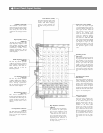
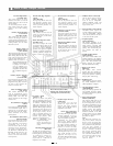

Foldback Control (FB)
The Foldback control deter-
mines the level of signal assign-
ed to the foldback mixing buss,
thus setting the level of that
channel in the on-stage monitor
mix.
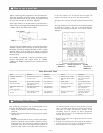
High Equalizer Control
(HIGH EQ)
The high EQ control alters the
high frequency response of the
input channel, providing ±13dB
at 10kHz, and ±15dBat 20kHz of
continuously variable active
shelving equalization. The "0"
detented position provides flat
audio response.
Middle Equalizer Control
(MID
EQ)
The mid EQ control provides
±15dB of continuously variable
active peaking equalization at
2kHz. and has a flat audio re-
sponse when set to the "0"
detented position.
Low Equalizer Control
(LOW
EQ)
The low EQ control provides
±13dB at l00Hz and ±15dB at
50Hz (of continuously variable
active shelving equalization.
The "0" detented position pro-
vides flat audio response.
Reverb/Effects Control
(REV/EFF)
This
control
determines
the?
level of signal assigned to the re-
verb effects buss. Rotating the
control clockwise increases the
amount of reverb effect in that
channel.
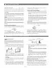
Low Impedance Connectors
(LOW
Z)
The XLR connectors are low im-
pedance, electronically balanced
inputs with an input impedance
of 1k ohms.
Peak Indicator (PEAK)
The peak indicator lights when
the pre or post EQ signal level
reaches 3dB below clipping,
giving a visual reference for
optimum setting of the trim con-
trol.
High Impedance Connectors
(HIGH Z)
These connectors are unbalanc-
ed, standard 1/4" phone jacks
with an input impedance? of 50k
ohms, and an input level of
—35dB when the trim control is
set to "10". When a plug is insert-
ed into the high —Z input, the cor-
responding XLR connector is
automatically switched out of
the input circuitry.
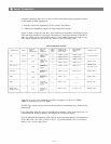
Input Trim Control (TRIM)
The input trim adjusts the gain
of the head-amp stage of the as-
sociated channel, providing 39
dB of gain control. When the
trim control is set to the "10"
position, the nominal input
levels of the low-Z and high-Z
inputs are — 55dB and —35dB re-
spectively. At the "0" position
the levels are -16dB and +4dB.
The trim of each channel should
be adjusted so that the peak LED
just begins to light, or only
flashes occasionally. This will
ensure lowest distortion levels
and optimum signal to noise
ratio.
Recording pan Pot
(REC
PAN)
This control assigns the record-
ing signal from each channel to
the recording L and R mixing
busses. At the center position,
the pan pot routes the signal
equally to the L and R mixing
busses. Panning from one side to
the other gradually assigns the
input signal to either the record-
ing L or R mixing bus exclusive-
ly!
Recording Level J Control
(REC LEVEL)
This control adjusts the level of
signal assigned to the tape deck
via the recording pan pot and
stereo L and R recording busses.
Rotating the control clockwise
increases the amount of signal
assigned to the recording L and R
busses and thus the level of that
input in the "recording mix."
Input Level Control
(INPUT LEVEL)
The level control provides con-
tinuously variable adjustment
of the channel output to the
program mixing buss, thus de-
termining the level of that
channel in the main sound
system mix. Since the reverb/
effects
signal
is
"post"
this
con-
trol, an increase in the level of the
channel's output will also result
in a corresponding increase in
he reverb effect of that channel.
The nominal level of the input
level control is at the "10" posi-
tion.
— 3 —
Front Panel, Input Section