


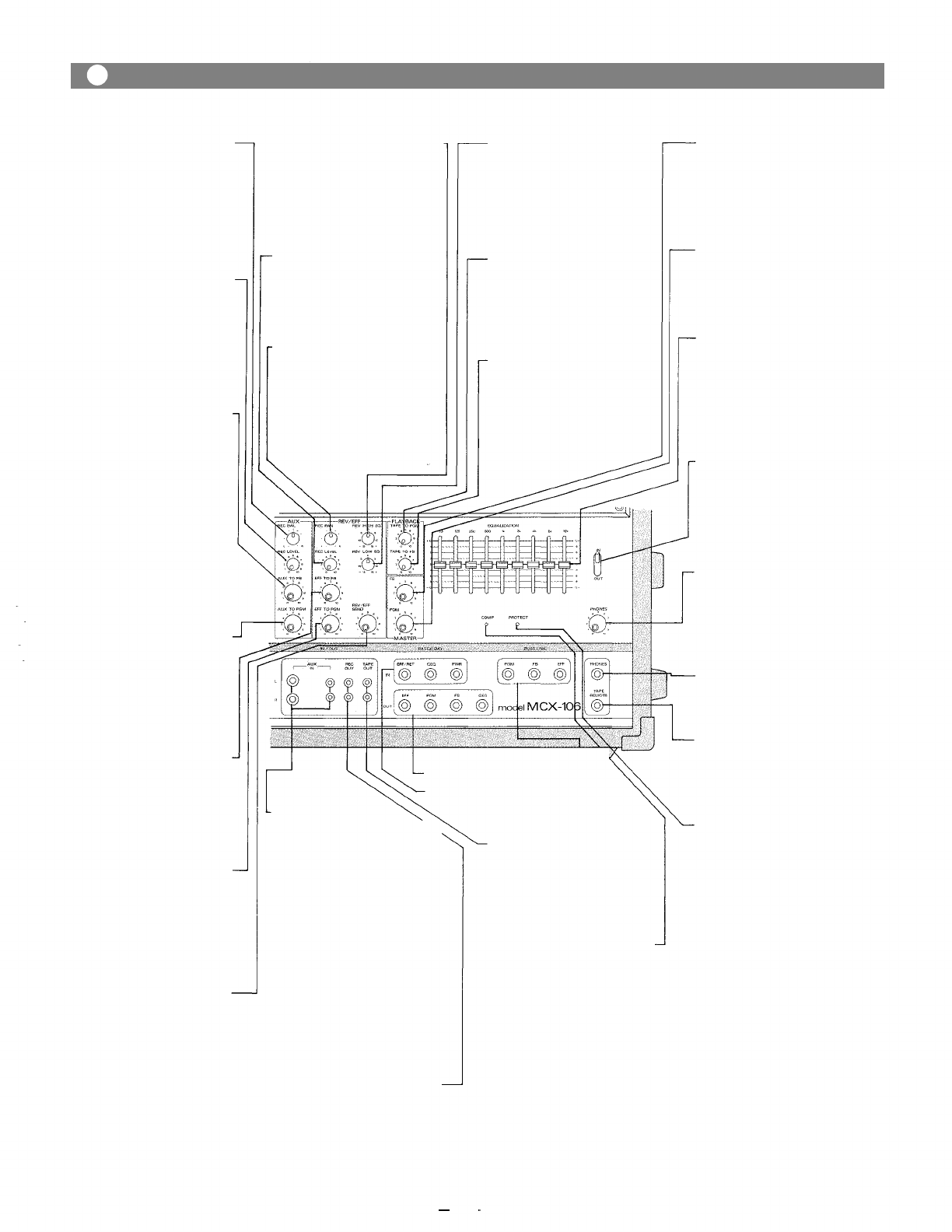
Aux Recording Balance
(AUX
REC
BAL)
This control adjusts the level
balance of the aux in, L and R
signals routed to the L and R
mixing busses.
At the center position, the bal-
ance control routes the signal
equally to the L and R mixing
busses.
Auxiliary Input Recording
Level Control
(AUX REC LEVEL)
This control sets the level of
stereo L and R signal (from an
external source connected to the
AUX INPUT) assigned to the re-
cording busses, via the AUX
REC BAL control.
Auxiliary Input to
Foldback Control
((AUX
TO FB)
This control sets the level of aux
input signal assigned to the fold-
back mixing bus, and thus the
level of the external aux source
in the on-stage monitor mix.
NOTE: If the aux source is a
stereo L and R signal (for
example, a stereo casset-
te player) the L and R
will be combined into
one mono signal before
assignment to either the
FB or PGM mixing bus-
ses.
Auxiliary Input to Program
Control
(AUX
TO
PGM)
This control sets the level of aux
input signal assigned to the
program mixing bus, and thus
the level of the external aux
source in the main mix.
Effect to Foldback Control
(EFF
TO FB)
This control determines the
level of reverb/effects return
signal assigned to the foldback
mixing buss, and thus the
amount of effects in the on-stage
monitor mix.
Reverb/Effects to Program-
Control
(EFF
TO
PGM)
This control adjusts the amount
of reverb/effects signal that is
returned to the program buss
and thus the level of reverb/
effects contained in the main
sound system.
Reverb/Effects Send Control
(REV/EFF SEND)
This control adjusts the overall
signal level of the effects mix
that is delivered to the internal
reverberation unit, or to an
external effects device through
the effects output. The send con-
trol works in conjunction with
the REV/EFF to PGM and the
REV/EFF to FB controls to set
the overall level of reverb/
effects in the main and monitor
sound systems.
Reverberation High Equalizer —
Control
(REV HIGH EQ)
The high EQ control alters the
high frequency response? of the
reverberation signal. The "0" de-
tented
position
provides
flat
audio response.
Recordig Level Control
(EFF REC LEVEL)
This control sets the level of
reverb (or external effects) in
the recording mix, via the effects
return pan pot.
Effect Recording Pan Control
(EFF
REC
PAN)
This control assigns the reverb
or external effects signal to the
recording L and R mixing bus-
ses. In the center "detended"
position, the signal is assigned
equally to L and R; panning the
control gradually assigns the
effect to either bus exclusively.
- Reverberation Low Equalizer
Control
(REV
LOW EQ)
The low EQ control alters the
low frequency response of the
reverberation signal. The "0" de-
tented
position
provides
flat
audio response.
- Playback to Program Control
(TAPE TO PGM)
This control adjusts the level of
playback signal routed to the
program mixing buss, and thus
the level of the internal tape?
source in the main mix.
Playback to Foldback Control
(TAPE TO FB)
This control adjusts the level of
playback signal to the foldback
mixing buss, and thus the level
of the internal tape in the on-
stage monitor mix.
Foldback Master Control (FB)
The FB master control adjusts
the overall combined signal
level of the six independent
channel foldback sends, and
thus the level of the entire on-
stage monitor mix.
Program Master Control (PGM)
The PGM control adjusts the
overall combined signal level of
the six independent channel
level controls, and thus the level
of the main sound system.
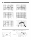
Graphic Equalizer
(EQUALIZATION)
The graphic equalizer is 1/1
octave with 9 independent active
bands (filters), providing 12dB
of boost or cut at each center fre-
quency. The "0" detented posi-
tion provides flat audio re-
sponse.
Graphic Equalizer In/Out
Switch (IN/OUT)
The in/out switch enables com-
parison
between
a
flat
response
(out) and the equalized response
(in). The "out" position com-
pletely removes the equalizer
from the MCX-106 circuitry.
Phones Level Control
(PHONES)
The phones level control
adjusts both the recording L
and R signals fed to the phones
output and permits recording
and playback monitoring.
Headphone Jack
The headphone jack will accept
any stereo headphone with 8
ohms impedance, or higher.
Tape Deck Remote Control
(TAPE REMOTE)
This jack remotely operates the
tape PAUSE function during
recording or playback by means
of a foot switch.
Power Amp Protection
Indicator (PROTECT)
The indicator LED lights if the
power amplifier output is short-
ed, if the temperature of the unit
rises above acceptable levels, or
if DG is drifted to the speaker
outputs. If the LED should light,
speaker wiring and ambient
temperature of the MCX-106
should be checked. If the LED
remains lighted, the unit should
be referred to qualified service
personnel for repair.
Note:
The MCX-106 protection cir-
cuitry will (1) detect 'faulty con-
ditions' within the power amp-
lifier, (2) give a visual indication,
and (3) automatically shut down
until the; fault condition is
alleviated. This special circuitry
ensures maximum reliability
and virtually eliminates equip-
ment damage due to unsafe or
fault
conditions.
Please
refer
to
fault protection table on page 9
for full explanation of this
important feature.
-Aux Input L and R
(AUX
IN, L, R)
The aux L and R 1/4" phone
jacks are unbalanced and accept
low and high impedance sources
at nominal —20 dB level. The
jacks are wired with the cor-
responding L and R pin jacks in
parallel. When a plug is inserted
in the phone jack, the pin jack is
automatically switched out of
the aux input circuitry. The aux
input is intended primarily for
external music sources such as
cassette tape players, radio
receivers, or record players.
NOTE: A phonograph with
magnetic cartridge re-
quires the use of a pre-
amp with RIAA equali-
zation.
Recording Output Pin Jack-
(REC
OUT)
The REC out pin jack derives its
signal from the recording L and
R mixing busses, and is intended
for connection to external re-
cording equipment. Nominal
output level is —10 dB with an
impedance of 1k ohms.
Playback Output Pin Jack
(TAPE OUT)
The playback o u t pin jack
obtains its signal from the
internal tape deck. Nominal
output level is 0dB dB with an
impedance of 1k ohms.
Power Amp Compression-
Indicator (COMP)
The comp LED lights when the
internal compressor is activat-
ed. The compressor is provided
to protect speaker systems by
compressing the input signal
level
of
the
power
amplifier
when clipping occurs in the out-
put stage. Frequent flashing of
the LED is not reason for alarm.
However. a constant or steady
light indicates that the MCX-106
is being overdriven and that the
internal
power
amplifier
is
pos-
sibly "under powered" (or that
application. The output level of
the; MCX-106 should be; decreas-
ed until the LED only flashes
intermittently.
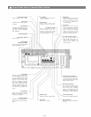
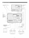
Buss Link Jack (BUSS LINK)
Patching Jack (PATCH BAY/OUT)
Patching Jack (PATCH BAY/IN)
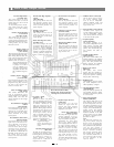
— 4
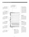
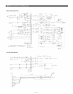
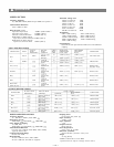
Front Panel, Output Section
—