


14 Chapter 6—Wordclocks
AD824—Owner’s Manual
6 Wordclocks
About Wordclocks
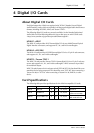
For correct operation and analog-to-digital conversion, it’s essential that the AD824 is
wordclock locked to the digital audio device connected to its SLOT output. The AD824
can generate a wordclock signal internally at either 44.1 kHz or 48 kHz, so it could be
used as the wordclock master, in which case the device connected to the SLOT would
be used as a wordclock slave. Alternatively, the AD824 can lock to an external wordclock
signal derived from its SLOT, or a wordclock signal received at the WORD CLOCK IN
connector.
See page 5 for information on selecting the wordclock source.
Wordclock Hookup Examples
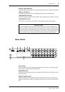
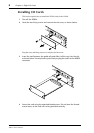
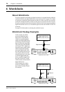
In this example, the AD824
sources its wordclock signal
from its SLOT. Note that the
AD824 is transmitting digital
audio to the digital audio device
and deriving a wordclock signal
from it all down the same cable.
This works okay with AES/EBU
and Tascam TDIF-1 digital con-
nections, because a single cable is
all that’s required to transmit
and receive digital audio. With
the ADAT format, however, sep-
arate optical cables are used to
transmit and receive, so in order
to transmit digital audio and
derive a wordclock signal, both
the ADAT IN and OUT on the
AD824 must be connected to the
digital audio device.
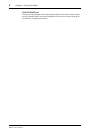
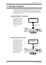
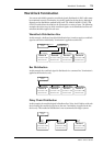
In this example, the AD824
sources its wordclock signal
from its BNC WORD CLOCK
IN connector.
Digital Audio Device
(DME32, 02R, D24, etc.)
MY8-xx
Digital I/O
Wordclock source = SLOT
AD824
WordclockDigital audio
ON OFF
POWER
AD CONVERTER
12345678
PEAK
SIGNAL
NOMINAL
PEAK
SIGNAL
+48V
SEL
NOMINAL
+48V
WORD CLOCK
INTERNAL
44.1kHz BNC SLOT48kHz
SEL
dB
GAIN
OFF ON
+48V MASTER
Digital Audio Device
(DME32, 02R, D24, etc.)
MY8-xx
Digital I/O
WORD CLOCK IN
Wordclock out
(BNC)
Wordclock source = BNC
AD824
Wordclock
Digital
audio
ON OFF
POWER
AD CONVERTER
12345678
PEAK
SIGNAL
NOMINAL
PEAK
SIGNAL
+48V
SEL
NOMINAL
+48V
WORD CLOCK
INTERNAL
44.1kHz BNC SLOT48kHz
SEL
dB
GAIN
OFF ON
+48V MASTER