


2
Chapter 2—Touring the AD824
AD824—Owner’s Manual
2 Touring the AD824
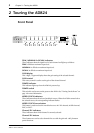
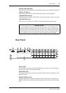
Front Panel
A
PEAK, NOMINAL & SIGNAL indicators
These indicators show the signal level of each channel and light up as follows:
PEAK
3 dB below maximum input level.
NOMINAL
14 dB below maximum input level.
SIGNAL
34 dB below maximum input level.
B
GAIN display
This 3-digit, 7-segment display shows the gain setting of the selected channel.
C
GAIN control
This rotary control is used to set the gain of the selected channel.
D
POWER indicator
This indicator lights up when the AD824 is powered up.
E
POWER switch
This switch is used to turn on the power to the AD824. See “Turning On the Power” on
page 1 for more information.
F
WORD CLOCK indicators
These indicators show the selected wordclock source. When the AD824 cannot lock to
the selected source, the corresponding indicator flashes.
G
WORD CLOCK Source button
This button is used to select the wordclock source: 44.1 kHz internal, 48 kHz internal,
BNC, or SLOT.
H
Channel SEL indicators
These indicators show which channel is currently selected.
I
Channel SEL buttons
These buttons are used to select channels for use with the gain and +48V phantom
power functions.
ON OFF
POWER
AD CONVERTER
12345678
PEAK
SIGNAL
NOMINAL
PEAK
SIGNAL
+48V
SEL
NOMINAL
+48V
WORD CLOCK
INTERNAL
44.1kHz BNC SLOT48kHz
SEL
dB
GAIN
OFF ON
+48V MASTER