


Wordclock Termination 15
AD824—Owner’s Manual
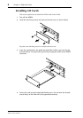
Wordclock Termination
For correct and reliable operation, wordclock signals distributed via BNC cables must
be terminated correctly. Termination is typically applied at the last device, although it
depends on the distribution method being used. The AD824’s WORD CLOCK 75Ω
ON/OFF switch allows the AD824 to be connected in a variety of ways. The following
examples show three ways in which wordclock signals can be distributed and how ter-
mination should be applied in each case.
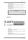
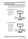
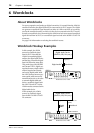
Wordclock Distribution Box
In this example, a dedicated wordclock distribution box is used to supply a wordclock
signal to each device individually. Termination is applied at each device.
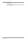
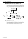
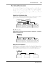
Bus Distribution
In this example, the wordclock signal is distributed via a common line. Termination is
applied at the last device only.
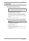
Daisy Chain Distribution
In this example, the wordclock signal is distributed in a “daisy-chain” fashion, with each
device feeding the wordclock signal on to the next. Termination is applied at the last
device only. This method of distribution is not recommended for larger systems.
Device-A
Termination = ON
Device-B Device-C Device-D
Termination = ON Termination = ON Termination = ON
WC OUT
(BNC)
Wordclock
master
Wordclock
distribution box
Wordclock slave Wordclock slave Wordclock slave Wordclock slave
WC IN (BNC) WC IN (BNC) WC IN (BNC) WC IN (BNC)
Device-A
Termination = OFF
Device-B Device-C Device-D
Termination = OFF Termination = OFF Termination = ON
Wordclock
master
Wordclock slave Wordclock slave Wordclock slave Wordclock slave
WC IN (BNC)
WC OUT (BNC)
WC IN (BNC) WC IN (BNC) WC IN (BNC)
Device-A
Termination = OFF
Device-B Device-C
Termination = OFF Termination = ON
Wordclock
master
Wordclock slave Wordclock slave Wordclock slave
WC IN
(BNC)
WC OUT
(BNC)
WC OUT (BNC)
WC IN
(BNC)
WC IN
(BNC)
WC OUT
(BNC)