


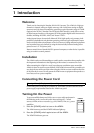
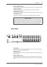

Rear Panel
3
AD824—Owner’s Manual
J
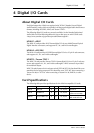
Channel +48V indicators
These indicators show whether the +48V phantom power is on or off for each channel.
K
+48V on/off button
This button is used to set the +48V phantom power for the selected channel.
L
+48V MASTER indicator
This indicator shows whether the MASTER +48V phantom power switch is on or off.
M
+48V MASTER switch
This switch is used to turn on and off the +48V phantom power master supply.
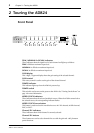
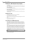
Rear Panel
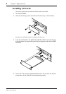
A
Power cable
The power cable is used to connect the AD824 to an AC outlet. See “Connecting the
Power Cord” on page 1 for more information.
B
COM RS422 port
This 9-pin D-sub connector is used to connect the AD824 to the next AD824 in a mul-
tiple-unit system.
C
COM PC/RS422 switch
This switch should be set to RS422 when the COM PC/RS422 port is connected to a
DME32 or the previous AD824 in a multiple-unit system, or PC when it’s connected to
a PC.
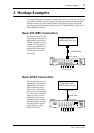
Security Cover
For certain applications you may wish to fit a protective cover over the AD824’s GAIN
controls and switches. Although Yamaha do not make such a cover, the AD824 has four
fixing holes to affix a custom-made cover. If you fit such a cover, make sure that the fixing
screws do not protrude inside the AD824 by more than 10 mm. The fixing holes accept
M3-size machine screws, and are spaced 45.0 mm vertically, 410 mm horizontally.
INPUT
(BAL)
OUT
(BAL)
IN
(BAL)
INSERT
COM
N
VERTER
AD824
8 2314567
8 2314567
8 2314567
SLOT
OUT
PC RS422
75Ω IN
ON
OFF
WORD CLOCK
RS422
6
8
J
K
2 3 4 5 7
91