


Changing the output patch settings
M7CL Owner’s Manual
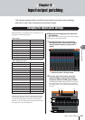
Input/output patching
9
107
• FEET (1127.26ft/s)
...........The delay time is shown as a dis-
tance in feet, calculated as the
speed of sound (1127.26 feet/s) at
an air temperature of 20
°
C (68
°
F)
multiplied by the delay time (sec-
onds).
• SAMPLE
.........The delay time is shown as a num-
ber of samples. If you change the
sampling frequency at which the
M7CL operates, the number of sam-
ples will change accordingly.
• msec
...........The delay time is shown in units of
milliseconds. If this button is on, the
same value is displayed above and
below the delay time knob (
5
).
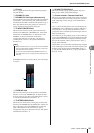
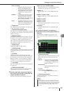
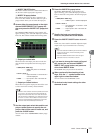
C
Output port
This indicates the type and number of the output port
to which the channel is assigned.
D
Channel select popup button
This button lets you select the channel that is assigned
to the output port. The name of the currently selected
channel is displayed.
E
Delay time knob
This knob sets the delay time of the output port. Press
this knob to select it, and use multifunction encoders
1–8 to adjust the settings. The millisecond value is
shown above the knob, and the delay time value in the
units selected in the DELAY SCALE field (
2
) is
shown below the knob.
F
DELAY button
Switches the output port delay on/off.
G
ø (Phase) button
Switches the phase of the signal assigned to the output
port between normal phase (black) and reverse phase
(orange).
H
ATT knob
Adjusts the amount of attenuation for the signal
assigned to the output port. To adjust this value, press
the knob in the screen to select it, and operate multi-
function encoders 1–8. You can adjust the setting in
0.1 dB steps over a range of -96 to +24 dB. The cur-
rent value is shown immediately below the knob.
I
Level meter
This meter indicates the level of the signal assigned to
the output port.
J
Output port select tabs
These tabs switch the output ports controlled in the
popup window in groups of up to eight ports.
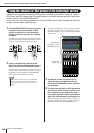
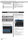
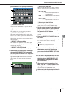
3
Use the output port select tabs at the bot-
tom of the popup window to select the out-
put port you want to control.
Each tab corresponds to the following output ports.
●
ES 1–8, 9–16, 17–24 (M7CL-48ES)
These tabs enable you to control EtherSound output
channels 1–8, 9–16 and 17–24 respectively.
●
OMNI 1–8
This tab enables you to control OMNI OUT jacks
1–8.
●
OMNI 9–16 (M7CL-32/48)
This tab enables you to control OMNI OUT jacks
9–16.
●
SLOT1 1–8, 9–16
●
SLOT2 1–8, 9–16
●
SLOT3 1–8, 9–16
These control output channels 1–8 and 9–16 of slots
1–3 respectively.
●
2TR OUT
Control the L/R channels of the 2TR OUT DIGI-
TAL jack.
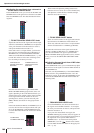
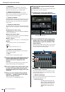
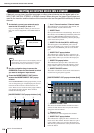
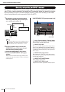
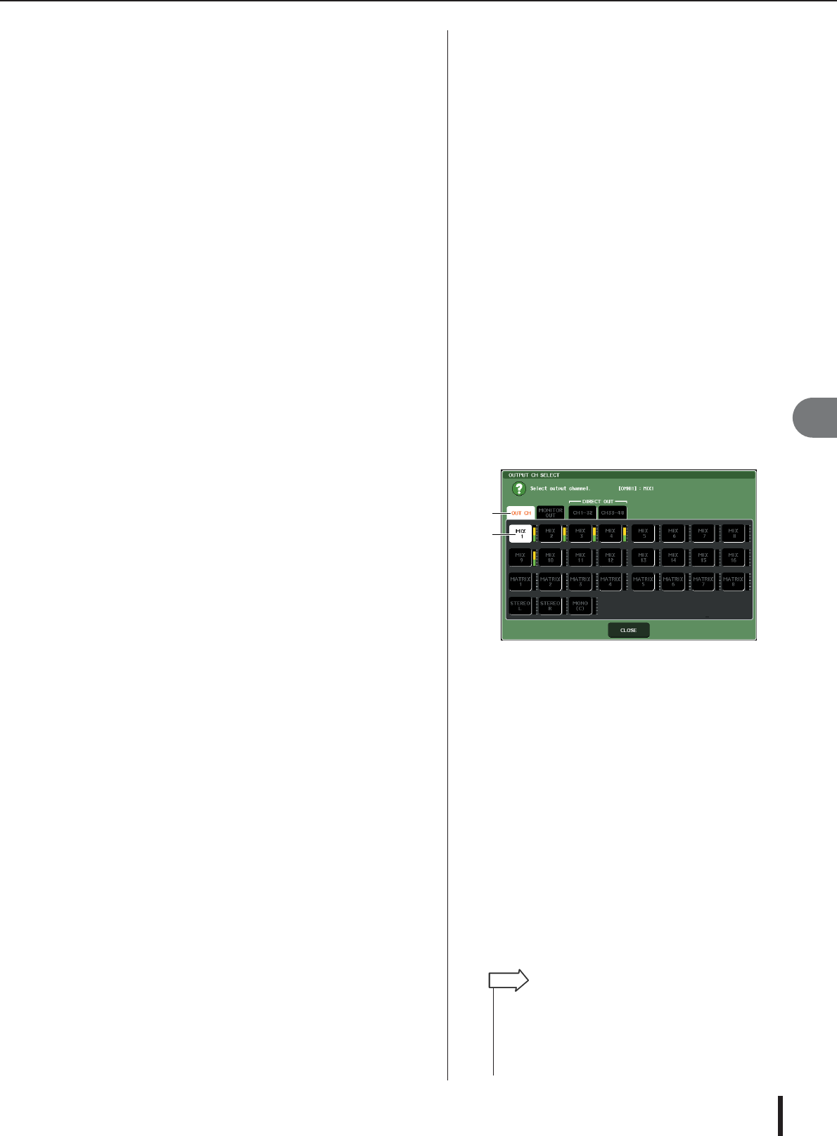
4
To assign a channel to an output port,
press the channel select popup window for
that port.
The OUTPUT CH SELECT popup window will
appear. The popup window includes the following
items.
1
Channel select tabs
These select the type of channel shown in the popup
window. Each tab corresponds to the following
channels.
• OUT CH
.......... Shows the output channels (MIX
channels 1–16, MATRIX channels
1–8, STEREO L/R channels, and
MONO (C) channel).
• MONITOR OUT
........... Shows the MONITOR OUT L/R/C
channels.
• CH 1–32
• CH 33–48 (M7CL–48/48ES only)
........... Shows INPUT channels 1–32 (1–
48)
B
Channel select button
Selects the channel to be assigned to the output port
you selected in step 3.
1
2
• If you selected CH 1–32 or CH 33–48 {M7CL–48 only}, the
input channel you selected will be output directly from the cor-
responding output port. At this time, the channel select button
in the OUTPUT PORT popup window is shown as “DIR CH
xx” (xx= channel number). (For details on direct output
→
p. 112).
HINT