


MW12CX/MW12C Owner’s Manual
Reference
16
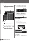
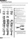
Front & Rear Panels
The following applies to both the MW12CX and MW12C. In cases where different features need to
be described for each model, the MW12CX feature will be described first, followed by the MW12C
feature in brackets: MW12CX (MW12C).
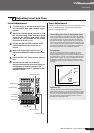
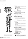
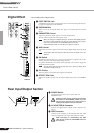
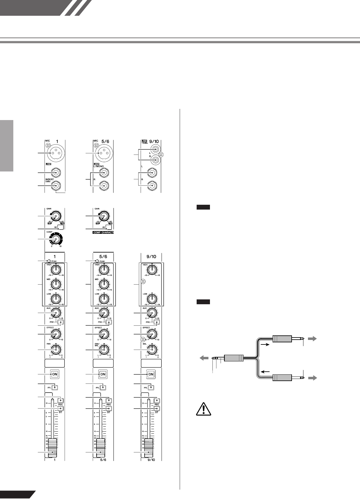
Channel Control Section
1 MIC Input Jacks (CHs 1 to 4, 5/6, 7/8)
These are balanced XLR-type microphone input jacks
(1:Ground; 2:Hot; 3:Cold).
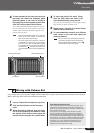
2 LINE Input Jacks (CHs 1 to 4)
These are balanced TRS phone-jack line inputs (T:Hot;
R:Cold; S:Ground).
You can connect either balanced or unbalanced phone plugs
to these jacks.
3 LINE Input Jacks (CHs 5/6 to 11/12)
These are unbalanced phone-jack stereo line inputs.
4 LINE Input Jacks (CHs 9/10, 11/12)
These are unbalanced stereo RCA pin jacks.
Where an input channel provides both a MIC input
jack and a LINE input jack, or a LINE input jack and
an RCA pin jack, you can use either jack but not both
at the same time. Please connect to only one jack on
each channel.
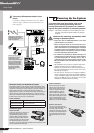
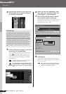
5 INSERT Jacks (CHs 1 to 4)
Each of these jacks provides an insert point between the
equalizer and fader of the corresponding monaural input
channel (CHs 1 to 4). The INSERT jacks are ideal for con-
necting devices such as graphic equalizers, compressors, or
noise filters into the corresponding channels. These are TRS
(tip, ring, sleeve) phone jacks that carry both the send and
return signal (tip = send/out; ring = return/in; sleeve =
ground).
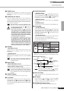
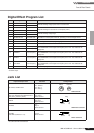
Patching external devices via an INSERT jack
requires a special insert cable such as illustrated
below (insert cable sold separately).
The signal output from the INSERT jacks is
reverse-phased. This should not be a problem
when connecting to an effect unit, but please be
aware of the possibility of phase conflict when
connecting to other types of device.
A reversed-phased signal may result in degraded
sound quality or even complete sound cancella-
tion.
1
2
5
6
8
A
C
D
E
H
I
9
0
7
B
F
G
1
6
A
C
D
E
H
I
9
0
3
7
B
F
G
A
C
D
E
H
I
0
3
4
B
F
G
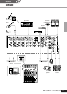
Channels
9/10 and 11/12
(Stereo)
Channels
1 to 4
(Monaural)
Channels
5/6 and 7/8
(Stereo)
MW12CX
NOTE
NOTE
To the INSERT I/O jack
To the input jack of the
external processor
Tip: OUT
Tip: IN
To the output jack of
the external processor
Sleeve (Ground)
Ring: IN
Tip: OUT
CAUTION