


Reference
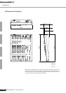
Front & Rear Panels
MW12CX/MW12C Owner’s Manual
21
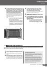
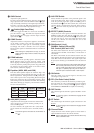
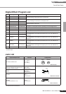
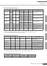
Digital Effect Program List
* “LFO” stands for Low Frequency Oscillator. An LFO is normally used to modulate another signal, determining the modulation speed and
waveform shape.
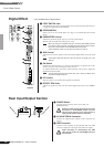
Jack List
* These jacks will also accept connection to monaural phone Connectors. If you use monaural phone connectors,
the connection will be unbalanced.
No Program Parameter Description
1 REVERB HALL 1 REVERB TIME
Reverb simulating a large space such as a concert hall.
2 REVERB HALL 2 REVERB TIME
3 REVERB ROOM 1 REVERB TIME
Reverb simulating the acoustics of a small space (room).
4 REVERB ROOM 2 REVERB TIME
5 REVERB STAGE 1 REVERB TIME
Reverb simulating a large stage.
6 REVERB STAGE 2 REVERB TIME
7 REVERB PLATE REVERB TIME Simulation of a metal-plate reverb unit, producing a more hard-edged sound.
8 DRUM AMBIENCE REVERB TIME A short reverb that is ideal for use with kick drum.
9 KARAOKE ECHO DELAY TIME Echo designed for karaoke (sing-along) applications.
10 VOCAL ECHO DELAY TIME Echo suitable for vocals.
11 CHORUS 1 LFO Frequency Creates a thick sound by modulating the delay time.
The PARAMETER control adjusts the frequency of the LFO* that modulates the
delay time.
12 CHORUS 2 LFO Frequency
13 FLANGER LFO Frequency
A sweeping pitched effect.
The PARAMETER control adjusts the frequency of the LFO* that modulates the
delay time.
14 PHASER LFO Frequency
Phase modulation produces a cyclical phasing effect.
The PARAMETER control adjusts the frequency of the LFO* that modulates the
delay time.
15 AUTO WAH LFO Frequency
A wah-wah effect with cyclical filter modulation.
The PARAMETER control adjusts the frequency of the LFO* that modulates the
delay time.
16 DISTORTION DRIVE Adds a sharp-edged distortion to the sound.
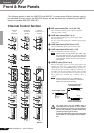
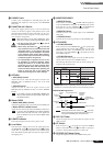
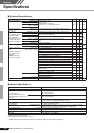
Input and Output Jacks Polarities Configurations
MIC INPUT, STEREO OUT
Pin 1: Ground
Pin 2: Hot (+)
Pin 3: Cold (-)
LINE INPUT (CH1 to 4)
REC OUT, STEREO OUT, MONITOR OUT,
AUX (AUX1), EFFECT (AUX2)*
Tip: Hot (+)
Ring: Cold (-)
Sleeve: Ground
INSERT
Tip: Output
Ring: Input
Sleeve: Ground
PHONES
Tip: L
Ring: R
Sleeve: Ground
RETURN
LINE INPUT (CH5/6 to 11/12)
Tip: Hot
Sleeve: Ground
OUTPUTINPUT
XLR Connector
TipSleeve
Ring
TRS Phone Connector
TipSleeve
Phone Connector