


Reference
Front & Rear Panels
MW12CX/MW12C Owner’s Manual
17
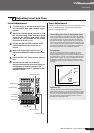
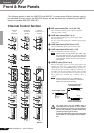
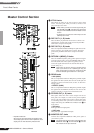
6 GAIN Control
Adjusts the input signal level.
To achieve the best balance between S/N ratio and dynamic
range, adjust the level so that the PEAK indicator
9 lights
only occasionally and briefly on the highest input transients.
The -60 to -16 scale is the MIC input adjustment range. The
-34 to +10 scale is the LINE input adjustment range.
7 Switch (High Pass Filter)
This switch toggles the HPF on or off. To turn the HPF on,
press the switch in ( ). The HPF cuts frequencies below
80 Hz (the HPF does not apply to the line inputs of stereo
input channels
3).
8 COMP Control
Adjusts the amount of compression applied to the channel.
As the knob is turned to the right the compression ratio
increases while the output gain is automatically adjusted
accordingly. The result is smoother, more even dynamics
because louder signals are attenuated while the overall level
is boosted.
Avoid setting the compression too high, as the the
higher average output level that results may lead to
feedback.
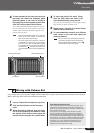
9 PEAK Indicator
The peak level of the post-EQ signal is detected, and the
PEAK indicator lights red when the level reaches 3 dB
below clipping. For XLR-equipped stereo input channels (5/
6 and 7/8), both the post-EQ and post-mic-amp peak levels
are detected, and the indicator lights red if either of these
levels reaches 3 dB below clipping.
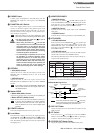
0 Equalizer (HIGH, MID, and LOW)
This three-band equalizer adjusts the channel’s high, mid,
and low frequency bands. Channels 9/10 and 11/12 have two
bands: high and low. Setting the knob to the ▼ position pro-
duces a flat response in the corresponding band. Turning the
knob to the right boosts the corresponding frequency band,
while turning to the left attenuates the band. The following
table shows the EQ type, frequency, and maximum cut/boost
for each of the three bands.
A AUX (AUX1) Control
Adjusts the level of the signal sent from the channel to the
AUX (AUX1) bus. The knob should generally be set
close to the ▼ position.
On stereo channels, the signals from the L (odd) and R
(even) channels are mixed and sent to the AUX (AUX1)
bus.
To send the signal to the buses set the ON switch to
on ( ).
B AUX PRE Switch
Selects whether the pre-fader or the post-fader signal is fed
to the AUX (AUX1) bus. If the switch is on ( ), the mixer
sends the pre-fader signal (the signal immediately prior to
the Channel fader
I) to the AUX (AUX1) bus, so that AUX
(AUX1) output is not affected by the fader. If the switch is
off ( ) the mixer sends the post-fader signal to the AUX
(AUX1) bus.
C EFFECT (AUX2) Controls
Adjusts the level of the signal sent from the channel to the
EFFECT (AUX2) bus. Note that the signal level sent to the
bus is also affected by the Channel fader
I. On stereo chan-
nels (5/6, 7/8, 9/10, or 11/12), the signals from the L (odd)
and R (even) channels are mixed and then sent to the
EFFECT (AUX2) bus.
D PAN Control (1 to 4)
PAN/BAL Control (5/6 and 7/8)
BAL Control (9/10 and 11/12)
The PAN control determines the stereo positioning of the
channel signal on the REC L and R buses or on the Stereo L
and R buses.
The BAL control knob sets the balance between left and
right channels. Signals input to the L input (odd channel) go
to the REC L bus or to the Stereo L bus; signals input to the
R input (even channel) go to the REC R bus or the Stereo R
bus.
On channels where this knob provides both PAN and
BAL control (channels 5/6 and 7/8), the knob oper-
ates as a PAN control when input is received via the
MIC jack or L (MONO) input only, and as a BAL con-
trol when input is received via both L and R inputs.
E ON Switch
Turn this switch on to send the signal to the buses. The
switch lights orange when on.
F PFL (Pre-Fader Listen) Switch
This switch lets you monitor the channel’s pre-fader signal.
Press the switch in ( ) so that it lights to turn it on. When
the switch is on the channel pre-fader
I signal is output to
the PHONES and MONITOR OUT jacks for monitoring.
G REC Switch
This switch assigns the channel’s signal to the REC L and R
buses.
To send the signal to the REC bus engage the ON
switch ( ).
H ST Switch
This switch assigns the channel’s signal to the Stereo L and
R buses.
To send the signal to the Stereo bus engage the ON
switch ( ).
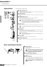
I Channel Fader
Adjusts the level of the channel signal. Use these faders to
adjust the balance between the various channels.
Set the fader sliders for unused channels all the way
down to minimize noise.
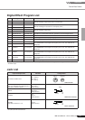
Band Type Frequency
Maximum
Cut/Boost
HIGH Shelving 10 kHz
±15 dBMID Peaking 2.5 kHz
LOW Shelving 100 Hz
NOTE
NOTE
NOTE
NOTE
NOTE
NOTE