


MICROMIX
MICROMIX
1
Introduction
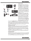
Thank you for purchasing the Yorkville Sound MP6D powered Mixer. We have coupled our
extensive experience in the development and production of powered mixers, (with state of the
art, computer assisted design technology) to create the smallest, lightest, and most powerful
combination mixer/amplifiers available. We at Yorkville Sound are confident that you will find
your new MP6D
to be an efficient and versatile solution to your mixer needs. This manual con-
tains information to help you get the maximum performance from your MP6D. We hope you'll
take the time to read it.
Input Channels
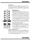
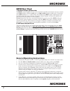
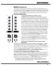
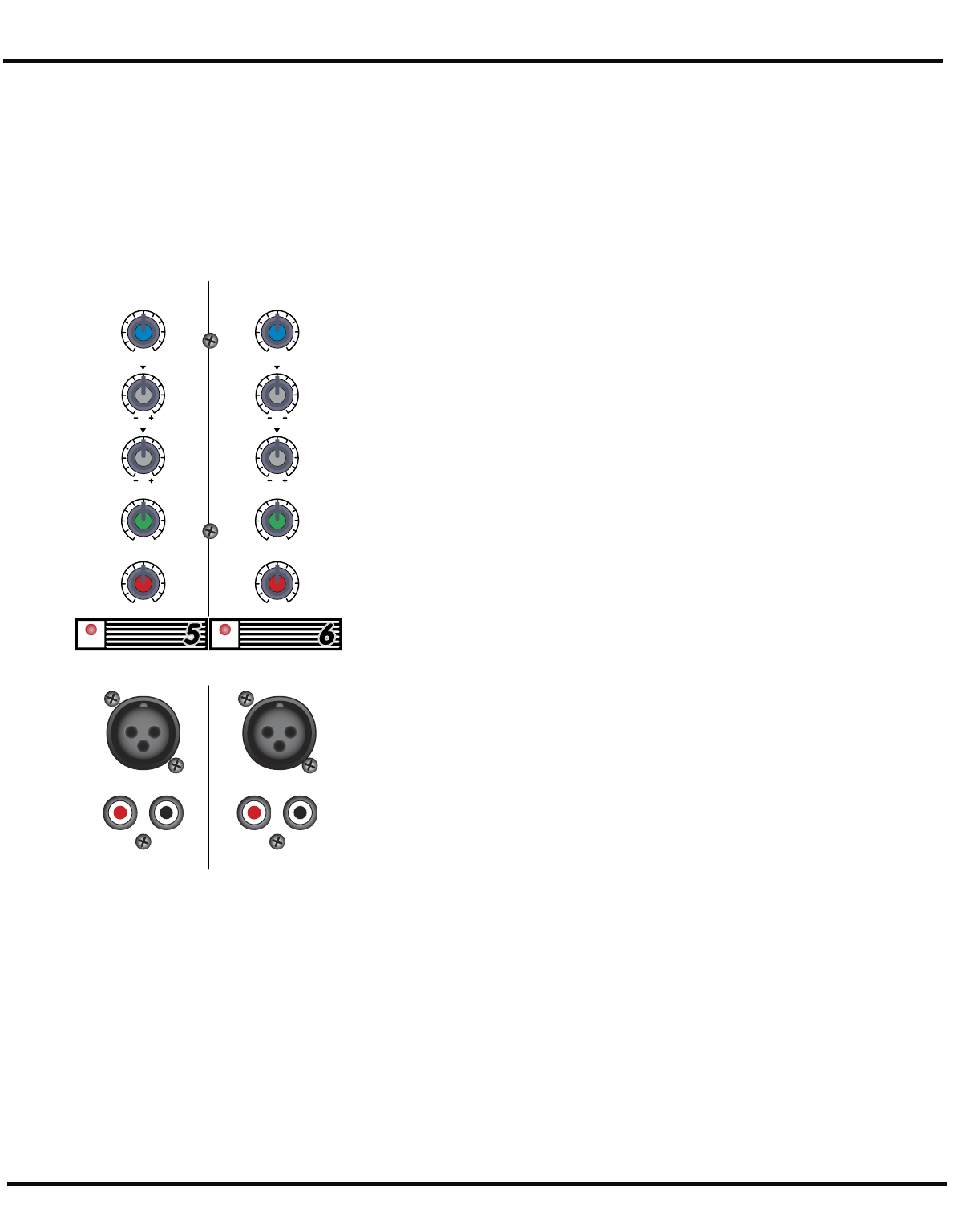
1. Microphone & Line Inputs
The MP6D
features standard XLR type low-impedance Mic In connectors on
all 6 channels. These microphone inputs are electronically balanced for maxi-
mum noise suppression and have characteristics matching all low impedance
dynamic microphones. 24 Volt DC phantom power is activated via the back-
panel Phantom push-button, this enables the MP6D
to use condenser micro-
phones. (Note: condenser and dynamic mics may be used together with the
Phantom power activated. It will not affect the performance of the dynamic
mics). Additionally, there are high-impedance 1/4-inch Bal Line In jacks on
channels 1 to 6. These are electronically balanced line-level inputs, but will
accept either balanced, or unbalanced input cables from high impedance
microphones, guitars, amplifier Line outputs, synthesizers, electric pianos,
etc. (Note: when connecting a balanced signal, employ balanced patch cables
with a ring-tip-sleeve (stereo) 1/4-inch plug on the mixer end). Channels 5
and 6 have dual Tape/CD/Line RCA-type inputs, (a phono preamplifier must
be connected to the MP6D
inputs for optimum turntable performance).
Do not connect signals to both types of inputs on any one channel (e.g.
the Mic and Line In's on channels 1 to 4 or the Mic and Tape/CD/Line In's
on channels 5 and 6). To do so will cause improper operation of the input
circuit. (Note: you may connect a stereo source to channels 1 through 4 but
you must use two channels, one for left and one for right).
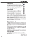
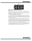
2. Channel Gain Controls & Clip LEDs
The Gain control has a range of 40dB. This adjustment determines both the
input sensitivity of the channel and the signal level sent to the Main mix-
ing bus*. (The MP6D's channel circuitry does not require separate gain and
level controls). The Clip LED is set to illuminate when the channel's overall
signal level is 3dB below the onset of actual clipping distortion. As a result,
small amounts of LED activity are acceptable; however, frequent or continu-
ous activity indicates the need to turn down the Gain control.
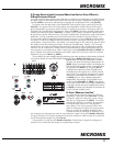
In audio terminology, a bus is a mix-down channel where all the signals
from the input channels are blended into one signal. The MP6D has three
busses, Main, Monitor and Effects.
3. Channel Low & High Equalization
The MP6D's Low and High EQ controls independently adjust the bass and treble frequencies
for each channel. The gain range for each control is plus or minus (+/-) 15dB to provide versa-
tile equalization consistent with the clean simplicity of the MP6D's design. As with all equal-
izers, boosts at one or more frequencies increase the channel's signal level. If the channel is
already at a fairly high operating level, this may cause clipping in which case the Clip LED will
light. Reduce the Gain setting and/or the EQ boosts if Clip activity is excessive.
Note: Center position reflects a neutral or flat EQ control setting; however, lower EQ control settings may
be effectively employed to reduce feedback and/or distortion).
CLIP CLIP
TAPE/CD/LINE INTAPE/CD/LINE IN
MIC
IN
EFX
HIGH
5
6
10
4
0
73
19
82
5
6
10
4
0
73
19
82
5
6
10
4
0
73
19
82
3
15
3
15
66
12 12
99
3
15
3
15
66
12 12
99
LOW
GAIN
MON
MIC
IN
EFX
HIGH
5
6
10
4
0
73
19
82
5
6
10
4
0
73
19
82
5
6
10
4
0
73
19
82
3
15
3
15
66
12 12
99
3
15
3
15
66
12 12
99
LOW
GAIN
MON