


MICROMIX
MICROMIX
4
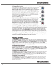
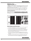
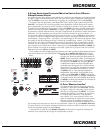
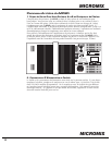
8. EFX Footswitch/Send Jack
This jack may be used to connect a standard on/off footswitch for the internal Digital Effects
Processor or alternately, as an effects send jack. In this latter function, it would send the signal so that
you could connect an external effects unit. If it is stereo, you would connect the unit's left and right
outputs to the dual RCA inputs on channel 5 or 6
(please note that the channel inputs are not in stereo
and that the stereo effect would be summed into a
mono mix). Here you would need to keep the Gain
level of that channel fairly low and make sure that its
EFX control is turned off. If the effects unit uses 1/4-
inch plugs, you could connect the output of the unit
to any one of the Balanced Line In jacks. As another
alternative, the EFX Footswitch/Send jack may be
used to deliver line-level signal to the input of an
auxiliary amp/speaker system, or a tape deck. Here,
the channel EFX controls would act as secondary level controls. Also keep in mind the channel EFX
send controls are post-Gain, so changes in the Gain settings will affect these levels as well.
9. Power LED & Switch
The Power LED lets you know that the MP6D is plugged in and turned on. The AC power on/
off switch is on the rear panel of the unit.
10. Phantom Power
The Phantom power LED indicates that 24 volts of DC phantom power is present on all the
XLR microphone inputs to power condenser microphones. Regular dynamic mics may be con-
nected while the Phantom Power is activated without encountering problems. The Phantom
Power push-button is located on the rear panel.
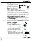
Digital Effects Processor
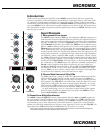
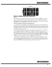
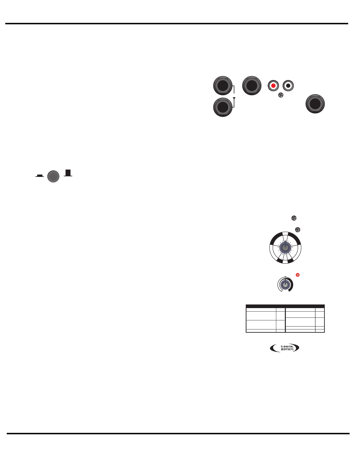
1. Select and MODIFY EFX Controls
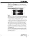
Use the EFX Selection control to choose from the sixteen 24-bit
digital reverbs, delays and other effects. This control rotates
continuously, which lets you rotate clockwise or counter-clock-
wise to select the desired effect. For convenience, a table of
the effects and their variables appear later in this manual and
on the front panel of the MP6D.
Parameters for each of the effects can be changed using the
MODIFY control which is located next to the Selection control.
For example, if a Hall reverb has been selected, the MODIFY
control will let you adjust the decay parameter. Choosing the
Chorus effect allows the chorus rate to be adjusted.
Note: The signal sent from the internal Digital Effects Processor to the
MON mix is independent from the MON send controls on the channel
strips. When a channel’s EFX control routes a signal to the internal
Effects processor and the MON level control (for that channel) is turned
off, the channel’s wet effects will still be audiable in the monitor bus (if
the EFX to MONitor return level is turned up).
2. Effects CLIP LED
Situated to the right of the MODIFY EFX control, the CLIP LED
indicates that the digital processor is receiving an input signal
that’s too strong, resulting in distortion. For optimum performance, the CLIP LED should never
flash. If there is clipping activity, turn down the channel EFX controls appropriately.
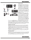
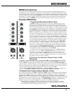
3. Effects Tables
See rear inside cover for the Series 1 effects tables.
LINE OUT
LINE IN
MAINS
MONITOR
LINE OUT
RECORD
OUT
FOOTSWITCH
/ SEND
EFX
Phantom
Power
on
off
CLIP
EFX
Modify
+
-
Room Reverb
Hall Reverb
Hall Reverb - Vocals
Hall Reverb w/Echo
Plate Reverb
Plate Reverb - Vocals
Plate Reverb w/Echo
Gated Reverb
decay
decay
decay
decay
decay
gain
pitch
delay
rate
1.
2.
3.
4.
5.
6.
7.
8.
9.
10.
11.
12.
13.
14.
15.
16.
Fast Echo
Short Decay Echo
Long Decay Echo
Chorus
Flanger
Rotary Speaker
Distortion
Harmonizer
ModifyEffect ModifyEffect
M
O
D
U
L
A
T
I
O
N
G
A
T
E
H
A
R
D
I
S
T
P
L
A
T
E
S
E
C
H
O
H
A
L
L
S
16
1
15
2 14
3 13
4 12
5 11
6 10
7 9
8
R
O
O
M
24