


3
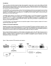
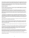
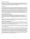
Figure 1. Basic principles of FM transmission and reception
Introduction:
The art and science of wireless microphone design have progressed in recent years to a point where reliable and flexible
performance can be taken for granted in even the most complex venues. What remains is for this level of performance to
become available at competitive prices and with easier setup requirements. AKG’s new WMS 61 and 81 wireless systems
go a long way toward achieving these goals.
The AKG WMS61 and 81 systems embody a number of technical attributes contributing to improved performance including
the following: long battery life (up to 12 hours for non-rechargeable batteries), automatic squelching via a pilot tone
imbedded in the transmitter signal, complementary 2-to-1 companding circuits, diversity reception, remote monitoring of
battery power, and overall ease of setup.
The WMS61 system operates in the VHF band, while the WMS 81 operates in the UHF band; otherwise, the two systems
are virtually identical in execution and performance. The available frequency sets for the WMS 61 correspond to TV
channels 7, 8, 9, 10, 11, 12 and 13. The available frequency sets for the WMS 81 correspond to TV channels 54, 55, 58
and 59. There are 15 adjustable frequency bands within each set. (See Ordering Information for added details on each
frequency set and regional requirements.)
In this White Paper we will discuss performance and operational aspects of these new systems, complete with hands-on
descriptions and system walk-through.
A Review of Technical Fundamentals:
Essentially, the heart of any wireless microphone is a miniature, low power FM (frequency modulation) transmitter. In fact,
some of the earliest wireless microphones operated on the commercial FM broadcast band and could be picked up with a
standard FM tuner! You can imagine the difficulties this caused in major cities where FM frequency broadcasting allocations
were plentiful and where the use of such microphones could interfere with nearby FM receivers.
Figure 1 shows the basic flow diagram for an FM modulation/demodulation system. Here, a RF (radio frequency) carrier is
generated, frequency-modulated by an audio signal, and then propagated through space. At the receiving end the carrier is
picked up, amplified, limited in amplitude to remove any effects of atmospheric electrical interference, and finally
demodulated to recover the audio signal.
A
B