


3. Mute indicator: When this red status light is on, the system is muted, indicating low or no RF signal from the
transmitter. The squelch action operates with a pilot tone from the transmitter and requires no manual adjustment at the
receiver. It is the level of this signal that automatically mutes the system, preventing a rise in noise when the RF signal is
low or non-existent.
4. RF level: This consists of a set of 5 LED status lights. When RF signal strength is high, all five are lit, and proper
operation is underway. When only the lowest light (yellow) is lit, there is minimal RF input to the system. This is an
indication to the operating engineer to take measures, such as changing channel assignments or rearranging the antenna
array, so that the RF level can be increased.
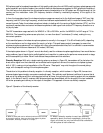
5. Diversity status, A and B: These LEDs indicate on an instantaneous basis which of the two internal diversity channels
is in operation. In normal use there should be nearly random switching back and forth between the two. If one of the
status lights remains on much of the time it is an indication that the operating engineer should slightly rearrange the
antennas or shift to another frequency. Constant switching of the LEDs indicate the receiver is searching for the signal,
and this the normal mode of operation.
6. AF level: The audio frequency level indicator shows the actual output of the receiver. Normal peak outputs should be
in the range of -4 to 0 dB, with the green LEDs on, and occasional peaking of the red LED. This level may be set with
the front panel volume control using the small screwdriver.
7. Channel selector: The channel selector is set with the small screwdriver and must match the channel set on the
transmitter. (Unlike the transmitter, you do not need to turn the receiver off when selecting a new frequency.)
Here are descriptions of the back panel controls:
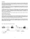
1. Antenna A and B connections. These are the BNC bayonet-type lock receptacles at the left and right edges of the back
panel. Insert the two “rabbit ear” antenna elements, pointing them upward and slightly outward. Adjust the length of the
antenna sections using the guide on the top of the receiver. Note that there are suggested antenna lengths for the various
transmission frequency master sets that are available for the WMS 61 and 81 product groups.
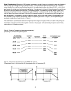
2. Signal outputs: You have your choice of three operating modes:
A. Line level unbalanced out at 1/4-inch receptacle.
B. Line level balanced. Use XLR-M receptacle with switch in “line” position.
C. Microphone level balanced. Use LR-M receptacle with switch in “mic” position.
3. Power in: Power for the SR 61 and 81 systems is normally by way of a wall 12 to 16 volt ac or dc power unit plugged
into the power receptacle on the back of the unit. Excess wire length may be looped around one of the small brackets for
strain relief. Power may also be supplied from the PS 61 or 81 through the antenna coaxial cable.
8