


4
FM has been used for broadcast transmission of high quality audio since the mid-1950s, and its primary advantages are wide
audio bandwidth and relative freedom from external electrical disturbances as compared to AM (amplitude modulation).
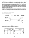
The chief factors that determine the ultimate performance characteristics of an FM system are RF signal strength at the
receiver and the modulation index (FM frequency deviation divided by modulating frequency) of the signal at the
transmitter.
In time, the transmission band for wireless microphone usage was moved out to the high-band ranges of VHF (very high
frequency) and UHF (ultra high frequency), where there has been ample bandwidth and, in most world areas, plenty of
unused channels. Today, the wireless microphone industry is dealing with the coming of digital television (DTV), and this
requires all manufacturers and users of wireless microphones to take a good look at actual TV frequency allocations on a
city by city basis.
The VHF transmission range used with the WMS 61 is 138 to 250 MHz, and for the WMS 81 the UHF range is 710 to
869 MHz. The transmitting antennas are quite short, no more than about 7 centimeters (3 inches), making for very
convenient operation.
The transmitted power of wireless microphone systems is normally in the range of 10 to 50 milliwatts (mW), depending
on the manufacturer and to a large extent the country of origin. This small power output is necessary to ensure that
wireless microphone systems will not interfere with other communications activities, but it is sufficient to accommodate
all line-of-sight activities over distances of 300 meters (1000 feet).
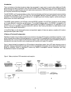
If the simple system shown in Figure 1 were to be directly used for wireless microphone applications, there would be two
major problems: loss of signal due to multiple paths from transmitter to receiver as the performer moves around on stage,
and the susceptibility to noise. We will now discuss these problems and their solutions.
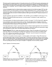
Diversity Reception: With only a single receiving antenna, as shown in Figure 2A, transmission will be lost when the
direct carrier signal from the transmitter and a reflected carrier signal both arrive at the receiver out-of-phase (a phase
shift of 180°), causing a virtual cancellation of the RF carrier. “Dead spots” may exist throughout the normal pickup
range, with consequent muting of the microphone system.
The solution to this problem is diversity reception. In diversity reception, which is shown in Figure 2B, there are two
antennas located approximately one-quarter wavelength apart. This relatively small distance is sufficient to ensure that at
least one of the antennas will be in a strong signal zone at all times, thus providing the receiving system with an adequate
signal. In the Series 61 and 81 receivers, both antenna signals are demodulated, and the stronger of the two is selected
for further processing and delivery to the output of the system. This approach is known as diversity reception.
Figure 2. Operation of the diversity receiver.
A. When a direct path and a reflected path are both received
at the single antenna, there may be some degree of phase
cancellation, resulting in weak or no output.
B. When a diversity receiver is used, two antennas,
spaced by about one-fourth wavelength, pick up the
signal, and there is a very low liklihood that cancellation
will take place at both antennas.