


Unpacking:
Every DJ Scan/RG™ has been thoroughly tested and has been shipped
in perfect operating condition, there is no assembly necessary. Carefully
check the shipping carton for damage that may have occurred during
shipping. If the carton appears to be damaged, carefully inspect your
unit for any damage and be sure all equipment necessary to operate
the unit has arrived intact. In case damage has been found or parts are
missing, please contact our toll free customer support number for fur-
ther instructions, please do not return the unit to your dealer.
Power Supply:
Before plugging your unit in be sure the source voltage in your area
matches the required voltage for your American DJ® DJ Scan/RG.™
The American DJ® DJ Scan/RG
™
is available in a 120v and 220v ver-
sion. Because line voltage may vary from venue to venue, you should
be sure to plug your unit into a matching wall outlet before attempting to
operate you controller.
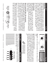
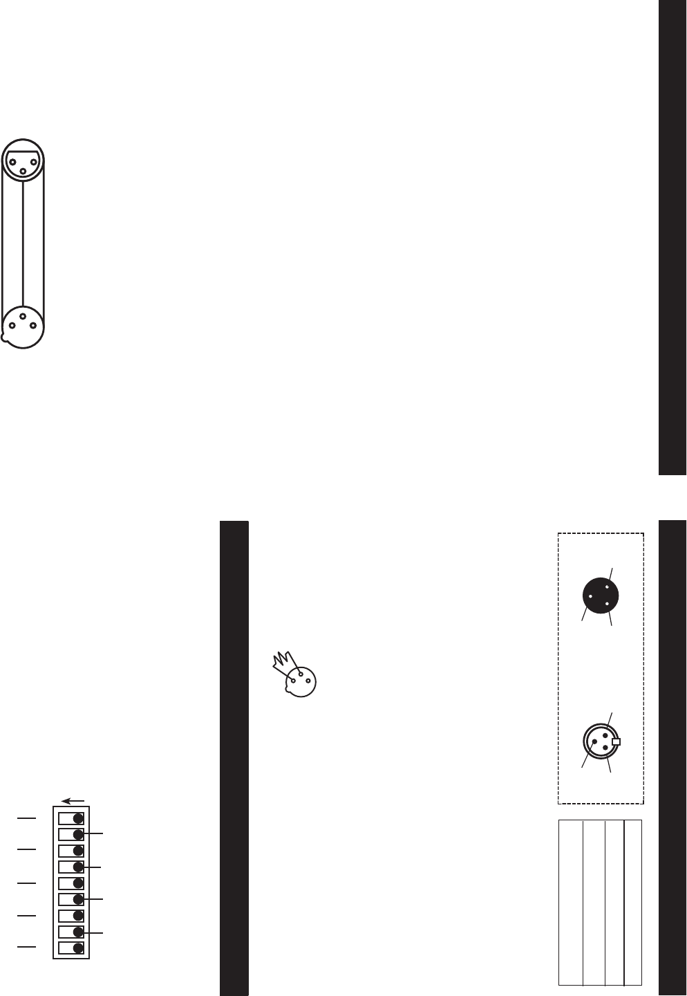
Data Cable (DMX Cable) Requirements:
Your controller and packs require a standard 3-pin XLR connector for
DMX data input and DMX data output (Figure 1). If you are making your
own cables be sure to use standard two conductor shielded cable (This
cable may be purchased at almost all pro sound and lighting stores).
Your cables should be made with a male and female XLR connector on
either end of the cable. Also remember that DMX cable must be daisy
chained and can not be “Y-d” or split.
Notice: Do not use the ground lug on the XLR connector. Do not con-
nect the cable’s shield conductor to the ground lug or allow the shield
conductor to come in contact with the XLR’s outer casing. Grounding
the shield could cause a short circuit and erratic behavior.
1
2
3
1
2
3
DMX +
DMX -
COMMON
DMX512 IN
CONNECTOR
3 PIN
DMX512 OUT
CONTROLLER
CONNECTOR
3 PIN
©American DJ Supply® - www.americandj.com - DJ Scan/RG™ Instruction Manual Page 5
DJ Scan/RG™ Set Up
Figure 2
DJ Scan/RG™ Set Up
©American DJ Supply® - www.americandj.com - DJ Scan/RG™ Instruction Manual Page 6
Notice: Be sure to follow fi gures two and three when making your own
cables.
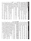
Special Note: Line Termination.
When longer runs of cable are used, you may need to use a terminator
on the last unit to avoid erratic behavior. A terminator is a 90-120 ohm
1/4 watt resistor which is connected between pins 2 and 3 of a male
XLR connector (DATA - and DATA +). This unit is inserted in the female
XLR connector of the last unit in your daisy chain to terminate the line.
Using a cable terminator will decrease the possibilities of erratic behav-
ior.
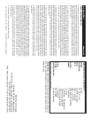
1
2
3
Termination reduces signal errors and
avoids signal transmission problems
and interference. It is always advisable
to connect a DMX terminal, (Resistance
120 Ohm 1/4 W) between PIN 2 (DMX-)
and PIN 3 (DMX +) of the last fixture.
Figure 4
1 Ground
1 Ground
XLR Male Socket
XLR Pin Confi guration
3 Hot
2 Cold
2 Cold
3 Hot
XLR Female Socket
Pin 3 = Data True (positive)
Pin 2 = Data Compliment (negative)
Pin 1 = Ground
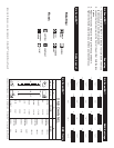
DJ Scan/RG™ DMX Addressing
DMX CHANNEL
123 547986
ON
1 4 16 64 256
2 8 32 128
DMX is short for Digital Multiplex. This is a universal binary language
used as a form of communication between intelligent fixtures. Each dip
switch represents a binary value.
Dip Switch 1 address equals 1
Dip Switch 2 address equals 2
Dip Switch 3 address equals 4
Dip Switch 4 address equals 8
Dip Switch 5 address equals 16
Dip Switch 6 address equals 32
Dip Switch 7 address equals 64
Dip Switch 8 address equals 128
Dip Switch 9 address equals 256
Figure 3
Figure 3