


12).
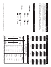
7. Please follow chart on page 12 for all slave dipswitch settings. Note
only one fixture may use the master units dip switch settings (see
Page 12).
8. After all the units settings have been set and are plugged in, adjust
the sensitivity knob on the bottom of the master unit to make them
react to sound.
9. To run a synchronized light show set all the dip switch on all the
fixture to the ‘off’ position. All fixtures will now run in the same
exact pattern.
10. You can also use the optional MINI/C Remote Control. If you want
to use the optional remote control, connect the MINI/C controller
to the first fixture in the line (master).
Note: The remote control only operates in Stand-Alone and Master/
Slave modes. If the remote is connected in DMX mode it will not
function. If the units do not receive an active DMX signal, the
units will automatically react to sound in the Master/Slave mode.
DMX Mode:
This fixture will react with DMX operation. For best results use only
one motor function for each scene (or step), when programming
scenes into a DMX controller. This will give you faster mirror and faster
gobo/color changes. For Example:
A. With DMX controller move the mirror up then program the step.
B. Move the mirror down then program that step.
C. Change the gobo/color wheel then program that step.
D. Continue this pattern to achieve best results.
1. Operating through a DMX controller gives the user freedom to
create his/her own programs tailored to their own individual needs.
This function also allows you to use your fixtures as spots.
2. This operation will allow you to control each individual fixtures traits
with a standard DMX 512 controller such as the American DJ Show
Designer™ or the American DJ
® DMX Operator.™
3. The DJ Scan/RG™ uses four DMX channels to operate; Channel 1
is Pan, channel 2 is Tilt, channel 3 is Color, and channel 4 Gobos.
4. To run your fixture in DMX mode, plug in the fixture via the XLR
connections to any standard DMX controller. - Follow the set-up
specifications that come with the controller.
DJ Scan/RG™ Operating Instructions DJ Scan/RG™ Operating Instructions
©American DJ Supply® - www.americandj.com - DJ Scan/RG™ Instruction Manual Page 8©American DJ Supply® - www.americandj.com - DJ Scan/RG™ Instruction Manual Page 7
Operating Modes:
You can use the DJ Scan/RG
™
in three ways:
• Stand alone mode - The unit will react to sound, chasing through
the several built in programs. You can also use the optional DJ
Scan MINI/C Remote Control to blackout the units.
• Master/Slave mode - You can daisy chain up to 4 units together to
get a synchronized light show that will react to sound chasing
through several built in programs.
• DMX control mode - This function will allow you to control each
individual fixtures traits with a standard DMX 512 controller such as
the American DJ Show Designer.
™
For best results use fog or special effects smoke to enhance the beams
projections. The DJ Scan/RG™ comes with a protective transportation
cover. Be sure to remove it before attempting any operation!
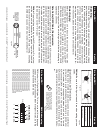
Stand Alone Mode:
1. To operate as a stand alone unit, via its internal chases and
microphone, turn all dip switches off (see Diagram 1).
2. Adjust the sensitivity knob on the bottom of the unit so the unit
will react to sound.
3. The DJ Scan/RG™ will now react to the bass sound of music via
the internal microphone.
Master-Slave Operation:
1. This function will allow you to link up to 16 units together to run on
the master unit’s 2 channel internal programs.
2. In Master-Slave operation one unit will act as the controlling unit
and the others will react to the controlling units programs. Any unit
can act as a Master or as a Slave.
3. Daisy chain your units via the XLR connector on the bottom
of the units.
4. Use standard XLR microphone cables to link your units together.
Remember that the Male XLR connector is the input and the
Female XLR connector is the output.
5. The first unit in the chain (master) will use the female XLR connec-
tor only - The last unit in the chain will use the male XLR connector
only.
6. Turn all the master units dip switches to the off position (see Page