


P
ower Supply:
Before plugging your unit in, be sure the source
voltage in your area matches the required voltage for your American
DJ
®
XP-3.™ Because line voltage may vary from venue to venue,
you should be sure your unit voltages matches the wall outlet voltage
before attempting to operate you xture.
DMX-512:
DMX is short for Digital Multiplex. This is a universal
protocol used as a form of communication between intelligent fixtures
and controllers.
A DMX controller sends DMX data instructions from
the controller to the fixture. DMX data is sent as serial data that
travels from fixture to fixture via the DATA “IN” and DATA “OUT” XLR
terminals located on all DMX fixtures (most controllers only have a
DATA “OUT” terminal).
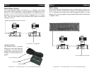
DMX Linking:
DMX is a language allowing all makes and models of
different manufactures to be linked together and operate from a single
controller, as long as all xtures and the controller are DMX compliant.
To ensure proper DMX data transmission, when using several DMX
fixtures try to use the shortest cable path possible. The order in which
fixtures are connected in a DMX line does not influence the DMX
addressing. For example; a fixture assigned a DMX address of 1 may
be placed anywhere in a DMX line, at the beginning, at the end, or
anywhere in the middle. When a fixture is assigned a DMX address of
1, the DMX controller knows to send DATA assigned to address 1 to
that unit, no matter where it is located in the DMX chain.
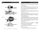
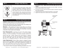
Data Cable (DMX Cable) Requirements (For DMX and Master/
Slave Operation):
The XP-3 can be controlled via DMX-512 proto-
col. The American DJ
®
XP-3™ is a ve channel DMX unit. The DMX
address is set on the side panel using the three function buttons
under the LCD. Your unit and your DMX control-
ler require a standard 3-pin XLR connector for
data input and data output (Figure 1). If you are
making your own cables, be sure to use standard
two conductor shielded cable (This cable may be
purchased at almost all pro sound and lighting
stores). Your cables should be made with a male
and female XLR connector on either end of the
cable. Also remember that DMX cable must be
daisy chained and can not be split.
©
American DJ
®
- www.americandj.com - XP-3™ Instruction Manual Page 6
©
American DJ
®
- www.americandj.com - XP-3™ Instruction Manual Page 5
Figure 2
Figure 1
DMX512 IN
3-PIN XLR
1
2
3
1
2
3
DMX +
DMX -
COMMO
N
DMX512 OUT
3-PIN XLR
Figure 3
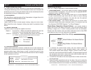
XP-3™ Set Up
1 Ground
1 Ground
XLR Male Socket
XLR Pin Con guration
3 Hot
2 Cold
2 Cold
3 Hot
XLR Female Socket
Pin 3 = Data True (positive)
Pin 2 = Data Compliment (negative)
Pin 1 = Ground
Special Note: Line Termination.
When longer runs of cable are
used, you may need to use a terminator on the last unit to avoid erratic
behavior. A terminator is a 90-120 ohm 1/4 watt resistor which is con-
nected between pins 2 and 3 of a male XLR connector (DATA + and
DATA -). This unit is inserted in the female XLR connector of the last
unit in your daisy chain to terminate the line. Using a cable terminator
(ADJ part number ZDMX/T) will decrease the possibilities of erratic
behavior.
XP-3™ Set Up
1
2
3
Te
rmination
r
educes
signal
e
rrors
and
avoids
signal
transmission
problem
s
and
interference.
It
is
always
advisable
to
connect
a
DMX
terminal,
(Resistance
120
Ohm
1/4
W)
between
PIN
2
(DMX-)
and
PIN
3
(DMX
+)
of
the
last
fixture.
Figure 4
Notice:
Be sure to follow gure three when making your own cables.
Do not use the ground lug on the XLR connector. Do not connect the
cable’s shield conductor to the ground lug or allow the shield conductor
to come in contact with the XLR’s outer casing. Grounding the shield
could cause a short circuit and erratic behavior.
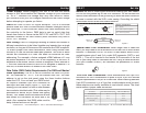
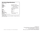
5-Pin XLR DMX Connectors.
Some manufactures use 5-pin XLR
connectors for DATA transmission in place of 3-pin. 5-pin XLR xtures
may be implemented in a 3-pin XLR DMX line. When inserting standard
5-pin XLR connectors in to a 3-pin line a cable adaptor must be used,
these adaptors are readily available at most electric stores. The chart
below details a proper cable conversion.
Conductor
5-Pin XLR Male (In)
3-Pin XLR Female (Out)
Pin 1
Do Not Use
Do Not Use
Pin 3
Pin 2
Pin 1
Pin 3
Pin 2
Not Used
Not Used
Data True (+ signal)
Data Compliment (- signal)
Ground/Shield
3-Pin XLR to 5-Pin XLR Conversion