


3‐2 Installation
3. Be sure drive operation is terminated and secured.
4. Remove all power sources from the control.
5. Wait at least 5 minutes for internal capacitors to discharge.
6. Refer to the control manual and remove the enclosure cover.
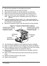
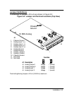
7. Open the control cover and locate Slots 1 & 2, see Figure 3‐1.
Note: Slot 3 is reserved for a feedback board only, encoder or
resolver.
8. Install the expansion board in Slot 1 or 2. Be sure the board is
securely pressed downward and makes good contact with the 48
pin connector in the slot position.
9. Secure the expansion board in the slot using the screw provided.
Figure 3‐1 Expansion Board Slot Locations
Feedback
Module Slot3
I/O Module
Slot1
I/O Module
Slot2
Installing board in Slot1
activates OP1 ANA 1 &
2 inputs & outputs.
Installing board in Slot2
activates OP2 ANA 1 &
2 inputs & outputs.
10. The mechanical installation of the expansion board is complete.
11. Refer to Jumper Definitions and configure the jumpers as desired.
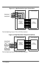
12. Refer to Figures 3‐3 and 3‐4 and complete the wiring of the Analog
Inputs and Outputs before you proceed to step 13.
13. When jumpers are set and connections are complete, close the
control cover.
14. Refer to the control manual and close and secure the enclosure
cover.
15. Restore all power sources to the control.
16. Restore drive operation.