


Installation 3‐3
Jumper Definitions
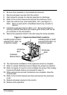
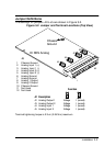
The settings for jumpers J2 to J5 are shown in Figure 3‐2.
Figure 3‐2 Jumper and Terminal Locations (Top View)
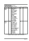
1 Chassis Ground
2 Analog Input 1 (+)
3 Analog Input 1 (-)
4 Analog Input 2 (+)
5 Analog Input 2 (-)
6 Analog Ground
7 Analog Ground
8 Analog 1 Output
9 Analog 2 Output
10 Chassis Ground
11 Not Used
12 Not Used
Chassis
Ground
HI RES Analog
J4
J5
J2
J3
J6
J6
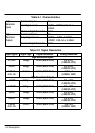
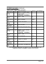
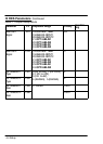
J2 Analog Output 1 Voltage I (current)
J3 Analog Output 2 Voltage I (current)
J4 Analog Input 1 Voltage I (current)
J5 Analog Input 2 Voltage I (current)
1
J# Description
Function
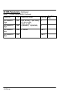
Terminal tightening torque is 2 lb‐in (0.24 Nm) maximum.